Condenser microphone
a condenser microphone and microphone body technology, applied in the field of condenser microphones, can solve the problems of complex unit configuration, high cost, and inability to control the sensitivities of individual condenser microphone units, and achieve the effects of simple configuration, large variation in sensitivity, and easy adjustmen
- Summary
- Abstract
- Description
- Claims
- Application Information
AI Technical Summary
Benefits of technology
Problems solved by technology
Method used
Image
Examples
first embodiment
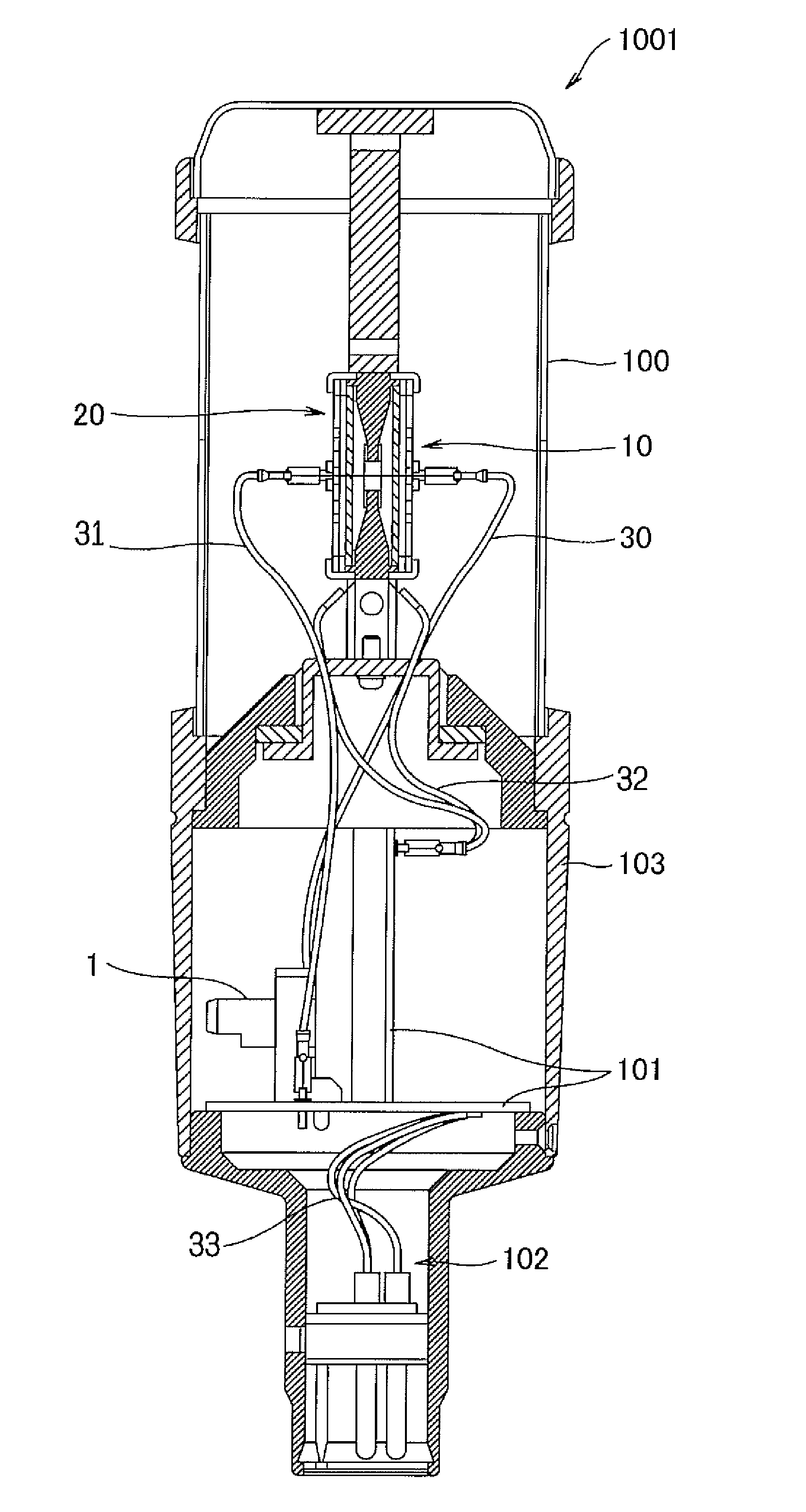
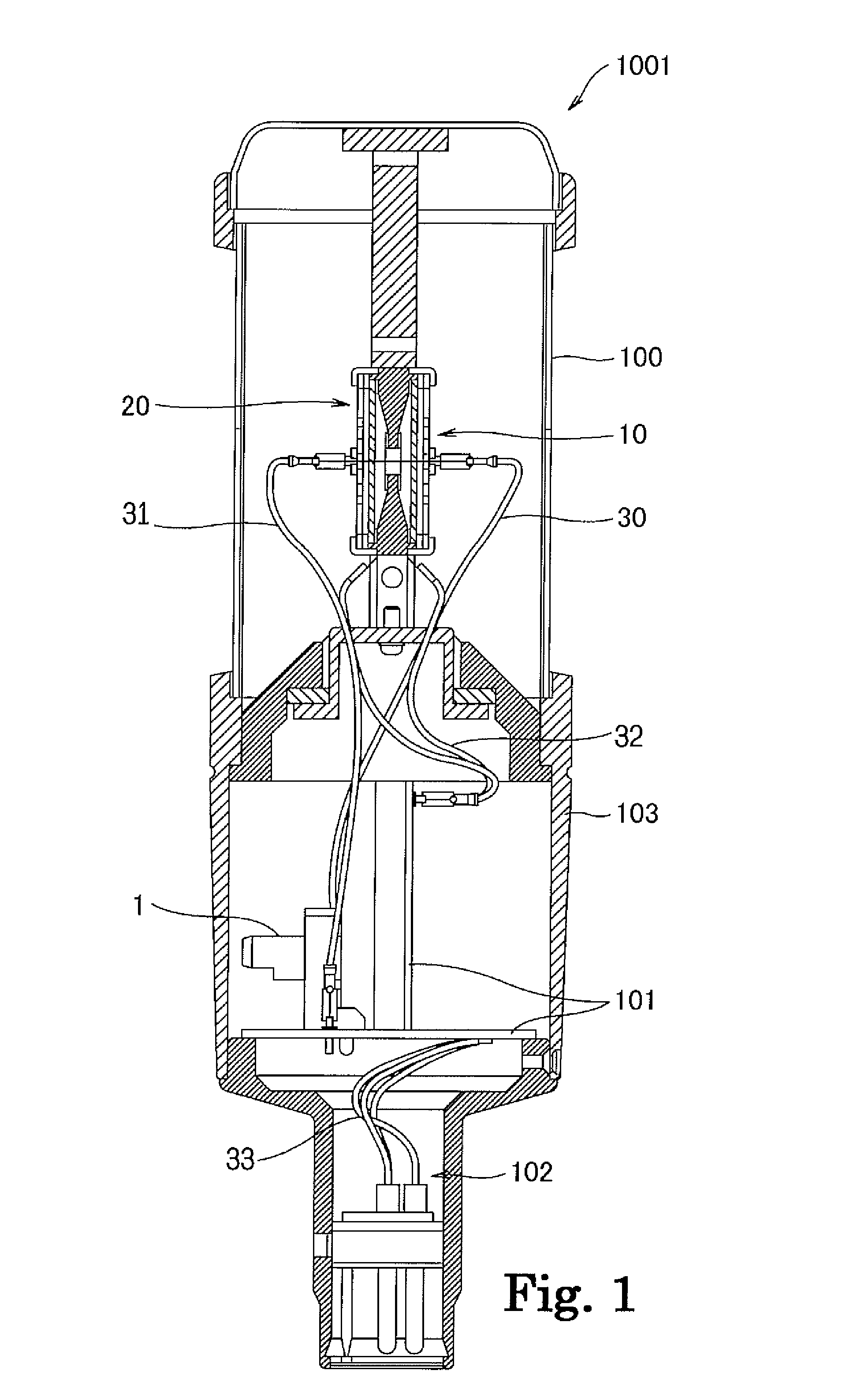
[0017]FIG. 1 shows a condenser microphone 1001 that includes condenser microphone units 10 and 20 each having a bottomed cylindrical shape; a sensitivity controller 1 and a circuit board 101 within a cylindrical housing 103; and a connector 102 that is protected by a cylindrical peripheral wall. In FIG. 1, the connector 102, the circuit board 101 and the sensitivity controller 1, and the condenser microphone units 10 and 20 are disposed in this order from the bottom. The condenser microphone units 10 and 20 are enclosed by a cylindrical microphone cover 100 having a net pattern for picking up a sound. A fixed member may be provided for reinforcement of the rigidity on a top (the upper side in FIG. 1) of the microphone cover 100, as shown in FIG. 1. The sensitivity controller 1 is electrically connected through wiring lines 30 to 33 to respective diaphragms 11 and 21 within the condenser microphone units 10 and 20. The sensitivity controller 1 may be disposed at any other position on...
second embodiment
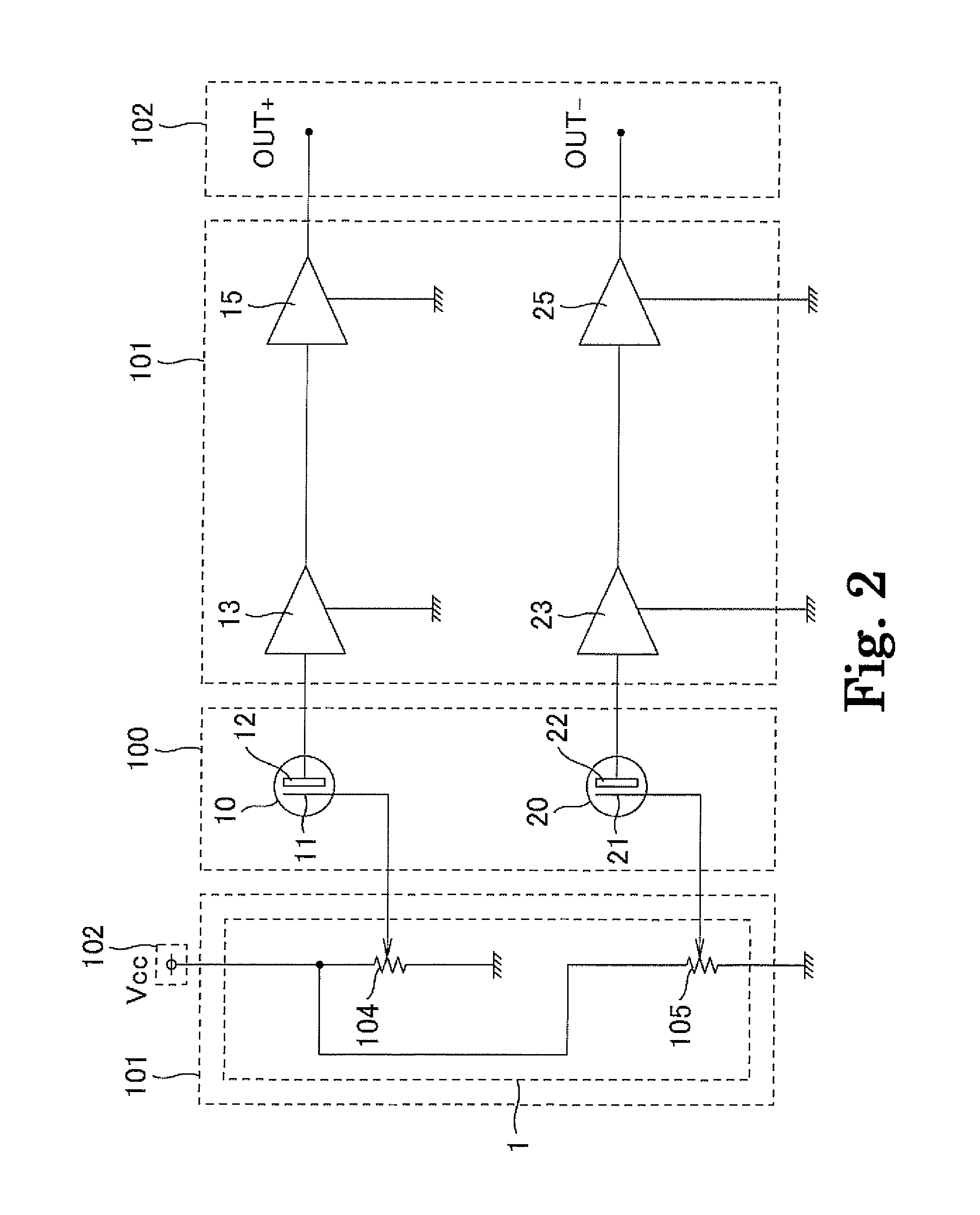
[0029]A second embodiment is now described with reference to FIG. 3. In the second embodiment, condenser microphone units are provided with a double variable resistor. In FIG. 3, variable resistors 104 and 105 are connected in parallel in mutually opposite directions between the power source Vcc and ground. Other circuit configurations are the same as that in the embodiment shown in FIG. 2 and omitted from the description.
[0030]In the embodiment shown in FIG. 3, upon operation of a common axis of the double variable resistor 104 and 105 configuring the double variable resistor, a voltage applied to a diaphragm of a first microphone unit increases while a voltage applied to a diaphragm of a second microphone unit decreases. This increases a polarization voltage of the first microphone unit, resulting in an increase in sensitivity of the first unit, and decreases a polarization voltage of the second microphone unit, resulting in a decrease in sensitivity of the second unit. The operat...
third embodiment
[0031]A third embodiment is now described with reference to FIG. 4. In the embodiment, a sensitivity controller 1 characteristic of the present invention is incorporated in a variable directional condenser microphone. The sensitivity controller 1 includes variable resistors 104 and 105 in correspondence to condenser microphone units 10 and 20 in the same way as the previous sensitivity controller 1 shown in FIG. 2. The microphone unit 10 functions as a front element, and the microphone unit functions as a back element for which the following directionality-switching circuit including an inverting amplifier 24 is provided between an impedance converter 23 and a buffer amplifier 25.
[0032]An inverting input terminal of the inverting amplifier 24 receives a signal output from the impedance converter 23 through an input resistance. The input resistance includes two input resistance elements Rs1 and Rs2 connected in series. A non-inverting input terminal of the inverting amplifier 24 is g...
PUM
 Abstract
Description
Claims
Application Information
 - R&D
- Intellectual Property
- Life Sciences
- Materials
- Tech Scout
- Unparalleled Data Quality
- Higher Quality Content
- 60% Fewer Hallucinations
Browse by: Latest US Patents, China's latest patents, Technical Efficacy Thesaurus, Application Domain, Technology Topic, Popular Technical Reports.
© 2025 PatSnap. All rights reserved.Legal|Privacy policy|Modern Slavery Act Transparency Statement|Sitemap|About US| Contact US: help@patsnap.com


