Amplitude flatness and phase linearity calibration for RF sources

a radio frequency and phase linearity calibration technology, applied in the field of signal sources, can solve the problems of inherently limited measurement, significant amplitude ripple in the up-conversion and filtering process, and deviation from linear phas

Inactive Publication Date: 2014-09-23
TEKTRONIX INC
View PDF8 Cites 5 Cited by
  • Summary
  • Abstract
  • Description
  • Claims
  • Application Information

AI Technical Summary

Problems solved by technology

The up-conversion and filtering process may create significant amounts of amplitude ripple and deviation from linear phase across the frequency bandwidth of interest for the desired wideband test signal.
However such measurement is inherently limited because the frequency response is subject to changes with temperature and age of components.

Method used


Image

  • Amplitude flatness and phase linearity calibration for RF sources
  • Amplitude flatness and phase linearity calibration for RF sources
  • Amplitude flatness and phase linearity calibration for RF sources

Examples


Embodiment Construction

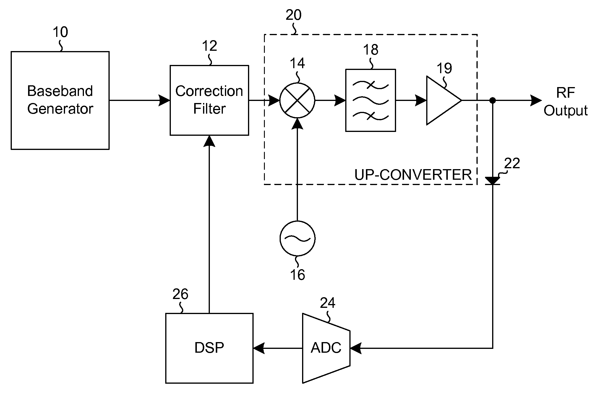
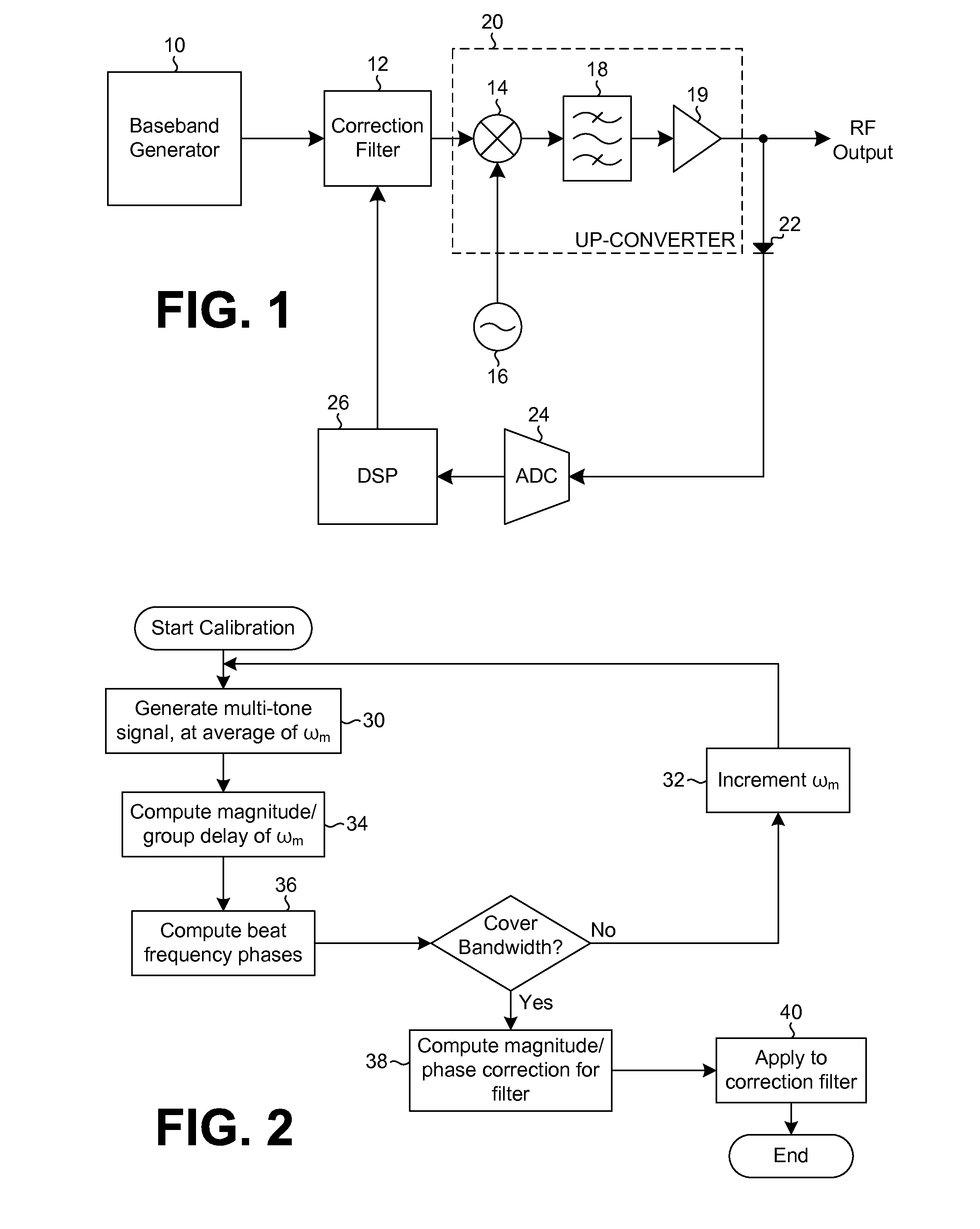
[0012]Referring now to FIG. 1, a baseband signal generator, such as an arbitrary waveform generator (AWG) 10, provides, as an output, at least a pair of tones that may be tuned across a frequency band of interest. Other architectures may include direct arbitrary waveform generation, up-conversion using an IQ modulator, IF up-conversion, etc. For the purposes of the following discussion, the two-tone implementation is described in detail.

[0013]The pair of tones from the baseband signal generator 10 is input to a magnitude and phase correction filter 12, such as a finite impulse response (FIR) filter, with the output of the filter being input to an up-converter stage 20. The up-converter stage 20 includes a mixer 14 which mixes the pair of tones with a frequency from a local oscillator 16. The output from the mixer 14 is input to an image rejection filter 18, the output of which is input to an output amplifier 19. The output from the output amplifier 19 is the desired RF output signal...


PUM


Abstract

An amplitude flatness and phase linearity calibration method for an RF source across a wide frequency bandwidth uses a simple square law diode detector and at least a pair of equal amplitude frequency tones. A baseband generator for the RF source generates the tones, which are applied in series to a correction filter and an up-converter to produce an output RF signal. The tones are stepped across a specified frequency bandwidth, and at each average frequency for the tones a magnitude and group delay is measured as well as a phase for the beat frequency between the tones. The resulting measurements are used to calibrate filter coefficients for the correction filter to assure amplitude flatness and phase linearity across the specified frequency bandwidth.

Description

BACKGROUND OF THE INVENTION[0001]The present invention relates to signal sources for testing electronic equipment, and more particularly to amplitude flatness and phase linearity calibration for radio frequency (RF) signal sources.[0002]A vector signal generator may be constructed using an arbitrary waveform generator (AWG) capable of wideband signal generation followed by one or more stages of block up-conversion and filtering. The up-conversion and filtering process may create significant amounts of amplitude ripple and deviation from linear phase across the frequency bandwidth of interest for the desired wideband test signal. These phase and magnitude effects are due to both the action of the filters and of the mixers themselves.[0003]The frequency response of the up-conversion process may be corrected by applying a baseband correction filter having a response which, when cascaded with the up-converter, provides a flat amplitude and linear phase over the frequency bandwidth of in...

Claims


Application Information

Patent Timeline
Patent Type & Authority Patents(United States)
IPC IPC(8): H04K1/02H04B1/04
CPCH04B1/0475H04B17/11H04B17/0037H04B17/104H04B17/0015H04B17/0085G01R29/08G01R29/10
Inventor DA, SILVA, MARCUS, K.
Owner TEKTRONIX INC
Why Eureka
Try Eureka