
Synthetic aperture radar smearing

a technology of synthetic aperture and radar, applied in the direction of camouflage devices, instruments, using reradiation, etc., can solve the problems of no effective way to conceal one's activities from the surveillance of radar, object is compromised, etc., and achieve the effect of modulation

Inactive Publication Date: 2014-09-16
MCDONNELL DOUGLAS
View PDF4 Cites 14 Cited by
  • Summary
  • Abstract
  • Description
  • Claims
  • Application Information

AI Technical Summary

Benefits of technology

The present invention is about a protective shield that is placed on an object to be protected. The shield is designed to influence the way incident RF pulses behave. The shield's electrical characteristics can be modified very quickly to change the RF pulses' electronic properties. This allows for the modification of electronic characteristics and the creation of a dual Doppler shift that can be detected by a radar system. The technical effect of this invention is the creation of a protective shield that can improve the object's safety and also enhance the radar system's detection capabilities.

Problems solved by technology

If that mapping information is combined with navigational information, indicating the position of objects on the map, as may be obtained from satellite navigation systems as example, the exact geographical position of the object may be made available to weapons operators, whether aircraft or artillery, and the object is compromised.
However, apart from accessing and disabling the radar, until the present invention, there was no effective way to conceal one's activities from the radar's surveillance.

Method used


Image

  • Synthetic aperture radar smearing
  • Synthetic aperture radar smearing
  • Synthetic aperture radar smearing

Examples


Embodiment Construction

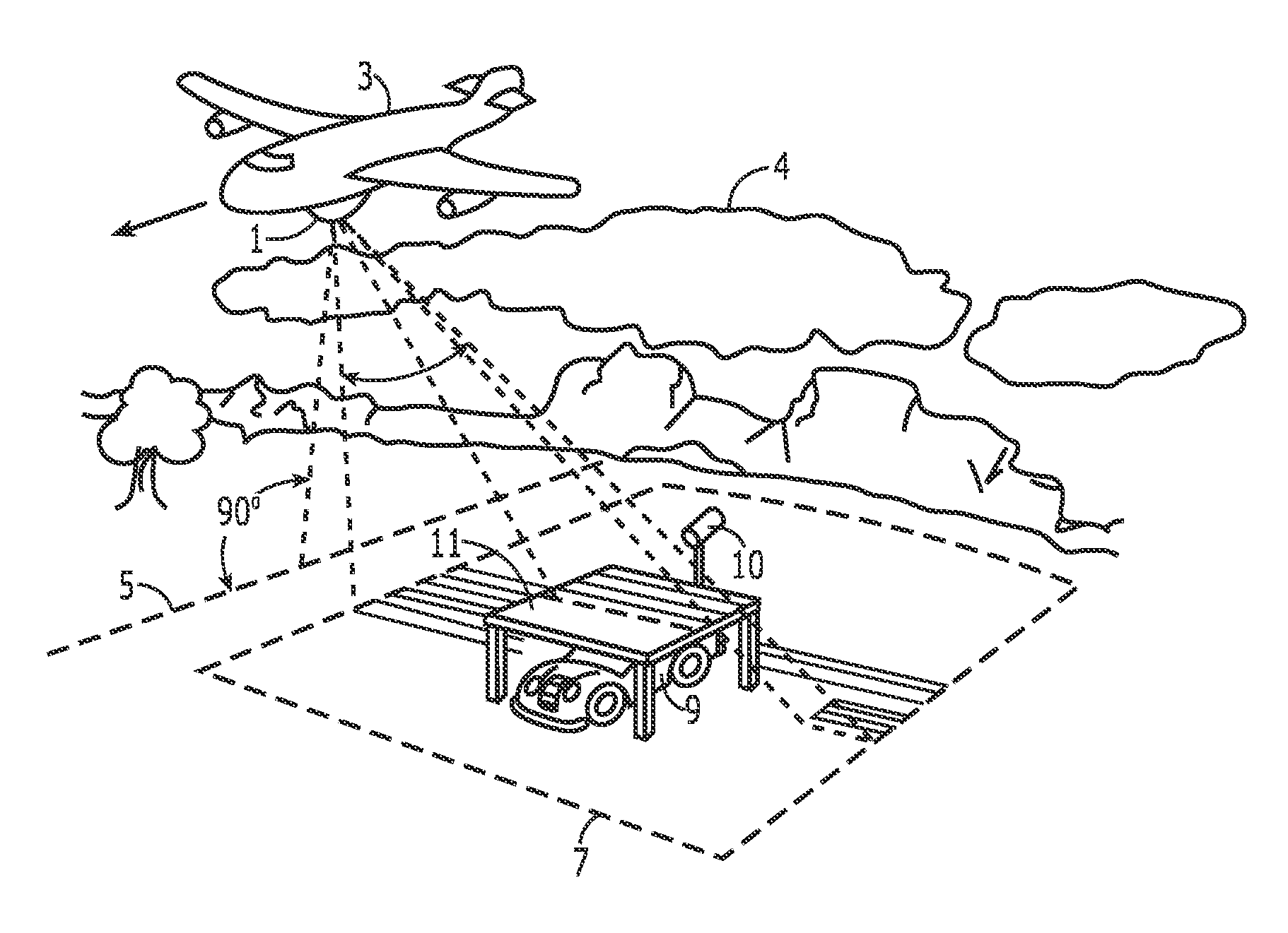
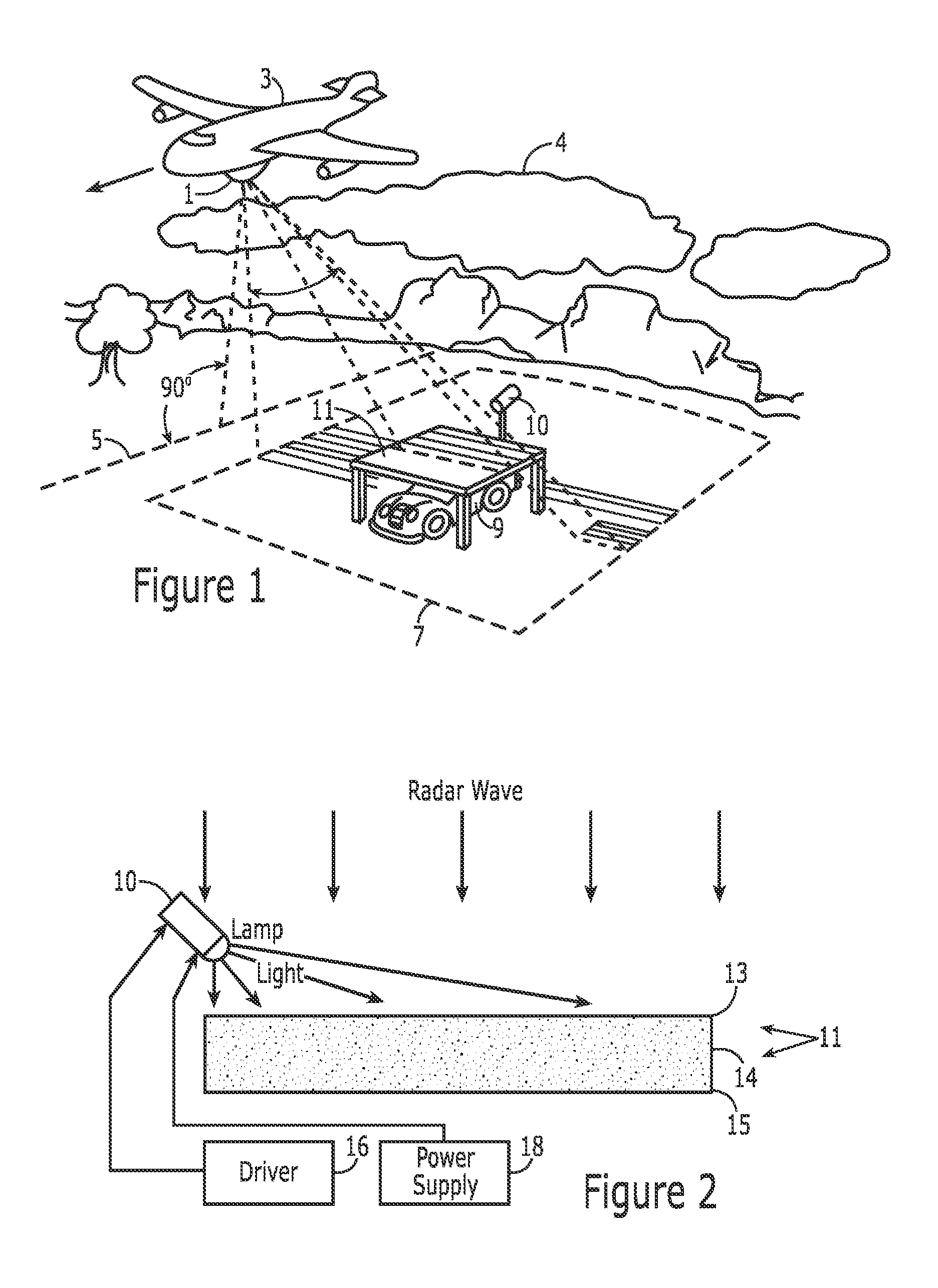
[0034]As generally represented in FIG. 1, radar 1, carried by aircraft 3, moves over the clouds 4 along a route indicated by dash line 5 on the ground surface. The radar “looks” sideways and down, its beam of pulsed RF extending sideways across a region of ground 7 to one side of the aircraft's route. As the aircraft travels forward, its radar continues to electronically view the region from slightly different celestial positions, as is conventional to synthetic aperture type radars. A truck 9, a potential target, is located within the region being surveyed. The truck however is garaged under cover of countermeasure shield 11, which is supported over the truck by posts of low reflectivity material, and, as hereafter described, remains effectively hidden from the radar. A light source 10, which may appear to the radar as a rock if the radar's resolution is sufficient to detect it, is mounted over and illuminates protective shield 11.

[0035]As viewed in the not to scale pictorial parti...


PUM


Abstract

A synthetic aperture radar's surveillance is defeated by electronic camouflage that employs a protective shield to cover an intended target. The shield intercepts and modifies the interrogating radar pulses by modulating incident radar pulses to produce radar echoes shifted in Doppler frequency, whereby the returned echoes give a false depiction of the target, even to smearing the radar display. New structures are presented that exhibit variable reflectivity and variable dielectric characteristics of particular use in the foregoing and other electronic systems.

Description

FIELD OF THE INVENTION[0001]This invention relates to a method and apparatus for electronically camouflaging vehicles and / or other potential targets to surveillance by synthetic aperture radar and, more particularly, to a device for smearing the radar's display, rendering potential targets unidentifiable. The invention also relates to devices for switching reflectivity levels to incident RF energy at high change rates.BACKGROUND[0002]Synthetic aperture radar, abbreviated SAR and sometimes referred to as a “look down” radar, is an instrument of choice for permitting aircraft and spacecraft, moving overhead, to monitor ground and naval operations occurring below. Such surveillance radar possesses the ability to “see” at night and the ability to see through fog and clouds, producing a map of the underlying surface topology as seen by the radar's emitted radar pulses. Presented on the radar's display, the map is of high resolution, permitting the radar operator to view essential buildin...

Claims


Application Information

Patent Timeline
Patent Type & Authority Patents(United States)
IPC IPC(8): H01Q17/00H01Q15/00F41H3/00F41H3/02G01S13/90H01Q15/14
CPCH01Q15/14H01Q17/002F41H3/00F41H3/02G01S13/90G01S7/38H01Q15/0006
Inventor JAMES, JESSE, CLOPTON
Owner MCDONNELL DOUGLAS
Learn More