
Arrangement with a steam turbine and a condenser

a technology of condenser and steam turbine, which is applied in the direction of steam engine plants, feed-water heaters, lighting and heating apparatus, etc., can solve the problems of increasing energy consumption with a low efficiency, difficult to set up a highly efficient cogeneration with a steam turbine, and more serious damage to the natural environment. achieve the effect of increasing the flexibility of the arrangement according to the invention, ensuring the effect of high efficiency and increasing the operating rang

Inactive Publication Date: 2014-09-16
CLEAN ENERGY SYST
View PDF9 Cites 1 Cited by
  • Summary
  • Abstract
  • Description
  • Claims
  • Application Information

AI Technical Summary

Benefits of technology

The invention relates to a system for generating energy using waste heat. The system includes a steam turbine, a condenser, a regenerative deheater, and a valve that controls the flow of feed-water through the deheater. The system is designed to be flexible and efficient, even with improper thermodynamic parameters. The system uses a mixture of oxygen and fuel to heat the feed-water before entering the steam turbine, which results in a high-quality steam output. The invention increases flexibility and efficiency of cogeneration using steam turbine and condenser.

Problems solved by technology

As the public attention to the harm to the natural environment increases energy consumption with a low efficiency is more and more criticized.
Even stricter handled is the emissions of nitro oxides, which are suspected to cause even more serious damage to the natural environment.
This very special process has several constraints and the waste heat has therefore very specific thermodynamic parameters, which make it difficult to set up a highly efficient cogeneration with a steam turbine.
So far, no concept is known to use waste heat not having proper conditions to operate a steam turbine with a high efficiency.

Method used


Image

  • Arrangement with a steam turbine and a condenser
  • Arrangement with a steam turbine and a condenser
  • Arrangement with a steam turbine and a condenser

Examples


Embodiment Construction

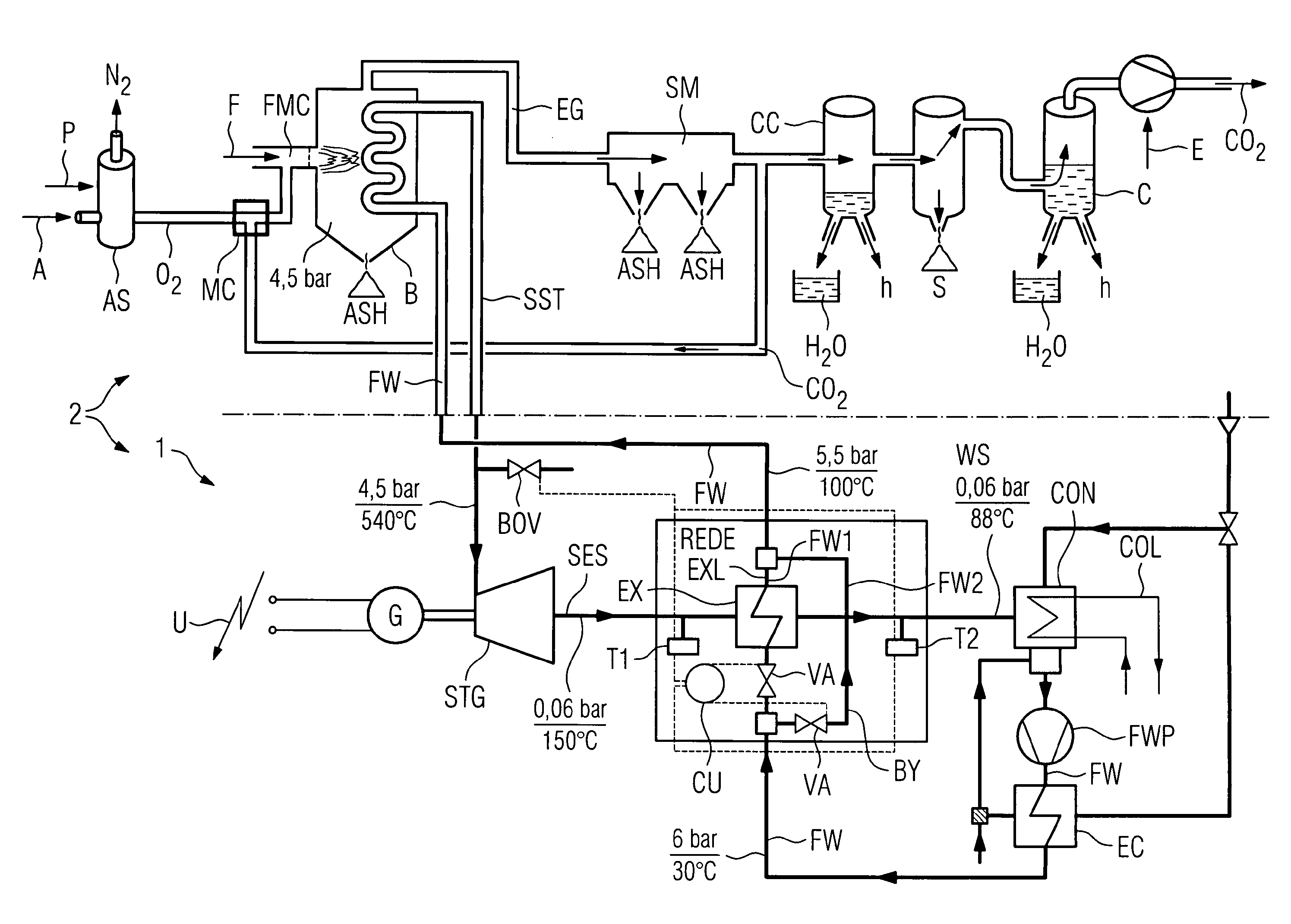
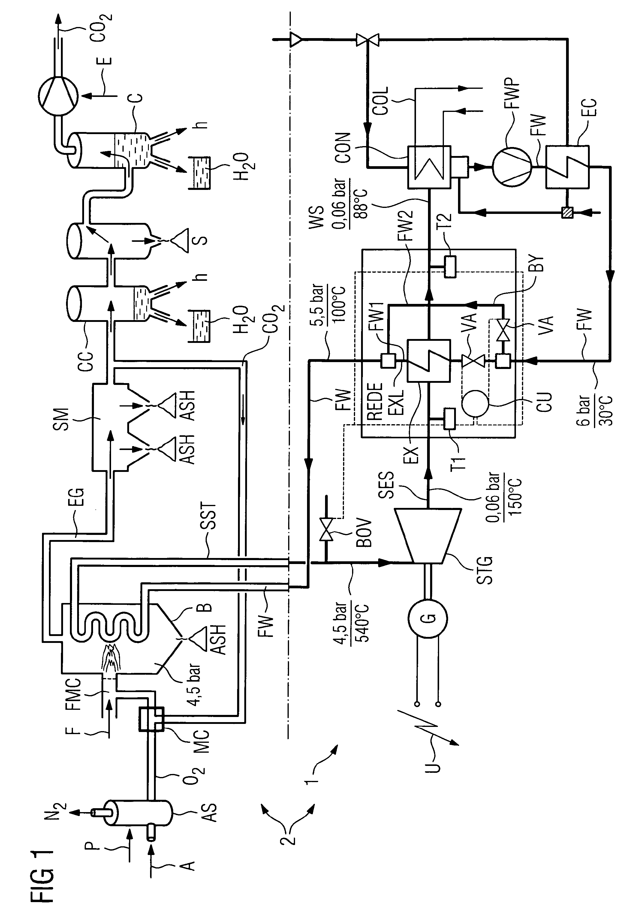
[0016]FIG. 1 shows a schematic flow diagram of an arrangement 1 according to the invention implemented into a power plant facility 2. The power plant facility 2 consumes air A and fuel F and generates carbon dioxide CO2 and electricity U.

[0017]Beginning in the upper left of the diagram air A enters an air separation AS, which separates the nitrogen N2 from the oxygen O2 consuming electrical energy P. The oxygen O2 is mixed with CO2 in a mixing chamber MC and enters a fuel mixing chamber FMC, where the mixture of O2 and CO2 is mixed with fuel F, which preferably consists of methane CH4. The nitrogen N2, which was separated from the air is compressed and liquefied, which is not shown in the diagram.

[0018]The mixture of FMC of fuel F, oxygen O2 and carbon dioxide CO2 is burned in a boiler B under a pressure of 4.5 bar. The exhaust gas EG of the burning process loses in first instance bigger particles of ash and in the following separation module SM finer particles of ash. After the ash...


PUM


Abstract

An arrangement including at least one steam turbine and one condenser is provided. Further, a method to operate such an arrangement is provided. A regenerative deheater is arranged in the steam flow between the steam turbine and the condenser, by which the steam, superheated exhaust steam, exiting the steam turbine is cooled down before entering the condenser and by which a feed-water stream is heated up.

Description

CROSS REFERENCE TO RELATED APPLICATIONS[0001]This application is the US National Stage of International Application No. PCT / EP2008 / 053813, filed Mar. 31, 2008 and claims the benefit thereof. The International Application claims the benefits of provisional patent application filed on Mar. 30, 2007, and assigned application No. 60 / 921,096. All of the applications are incorporated by reference herein in their entirety.FIELD OF INVENTION[0002]The present invention relates to an arrangement with at least one steam turbine and one condenser. Further the invention deals with a method to operate an arrangement according to the invention.BACKGROUND OF INVENTION[0003]As the public attention to the harm to the natural environment increases energy consumption with a low efficiency is more and more criticized. Especially the fossil generation of energy is in the focus of the critic since the carbon dioxide concentration in the atmosphere is increasing and is suspected to cause a green house effe...

Claims


Application Information

Patent Timeline
Patent Type & Authority Patents(United States)
IPC IPC(8): F01K7/42F01K7/34F01K7/38F22D1/32
CPCF01K7/38F01K7/345F01K7/42F22D1/32
Inventor HOFFMAN, LAWRENCEMACADAM, SCOTTTIELCKE, UDO
Owner CLEAN ENERGY SYST
Learn More