
Greenhouse, greenhouse climate control system and method of controlling greenhouse climate

a greenhouse climate and control system technology, applied in the field of greenhouses, can solve the problems of increasing the cost of such a system, requiring additional heating, and limiting the use of the closed greenhouse in first hand, and achieve the effect of reducing construction and use costs

Active Publication Date: 2014-09-09
FINN GROWERS OY
View PDF18 Cites 0 Cited by
  • Summary
  • Abstract
  • Description
  • Claims
  • Application Information

AI Technical Summary

Benefits of technology

This system achieves a 20-50% increase in yield by optimizing temperature, moisture, and carbon dioxide levels, reducing heating needs, minimizing water usage, and lowering construction and operational costs, while allowing for better light utilization and precise yield timing.

Problems solved by technology

In addition, ventilation to remove moisture has to be performed in spring and autumn, which requires additional heating.
The use of the closed greenhouse is in first hand restricted by the bad functionality or the high costs of the earlier solutions.
The costs required by such a system are of the above reasons considerable and it has not become very general in practice.
The big size of the required heat accumulator makes the whole system expensive and the system is not in common use.
Furthermore, the apparatus is not suitable for condensing moisture in the air, because there is only a water inlet but no outlet.
The above mentioned facts make the solution not suitable for greenhouse use.
Because of the way how the air and water meet, the speed is low, leading to a weak heat exchange.
As outer air is blown in the system in to the greenhouse, it is not suitable for cooling of a closed greenhouse.
Neither can excess moisture be removed from the greenhouse by means of this method, but the humidification of the air to be blown inside increases the need of removing moisture from the greenhouse by ventilation.
The apparatus is not generally suitable for cooling of greenhouses or removal of moisture.
The efficiency of the system is not sufficient to remove daily heat from a closed greenhouse.

Method used


Image

  • Greenhouse, greenhouse climate control system and method of controlling greenhouse climate
  • Greenhouse, greenhouse climate control system and method of controlling greenhouse climate
  • Greenhouse, greenhouse climate control system and method of controlling greenhouse climate

Examples


Embodiment Construction

[0034]The conditions differ essentially from each other during different seasons of the year in view of the climate control of greenhouse. The apparatuses and methods of the invention are especially useful in midsummer and also in spring and fall. In midsummer, when the radiation energy of the sun is biggest, the heat energy to be lead out from the greenhouse has its maximum and on the other hand the need for night heating is minimal.

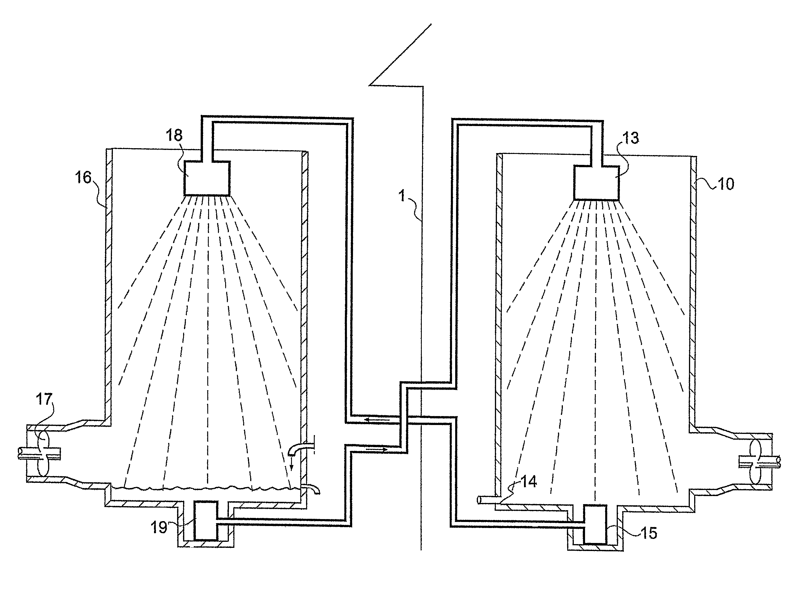
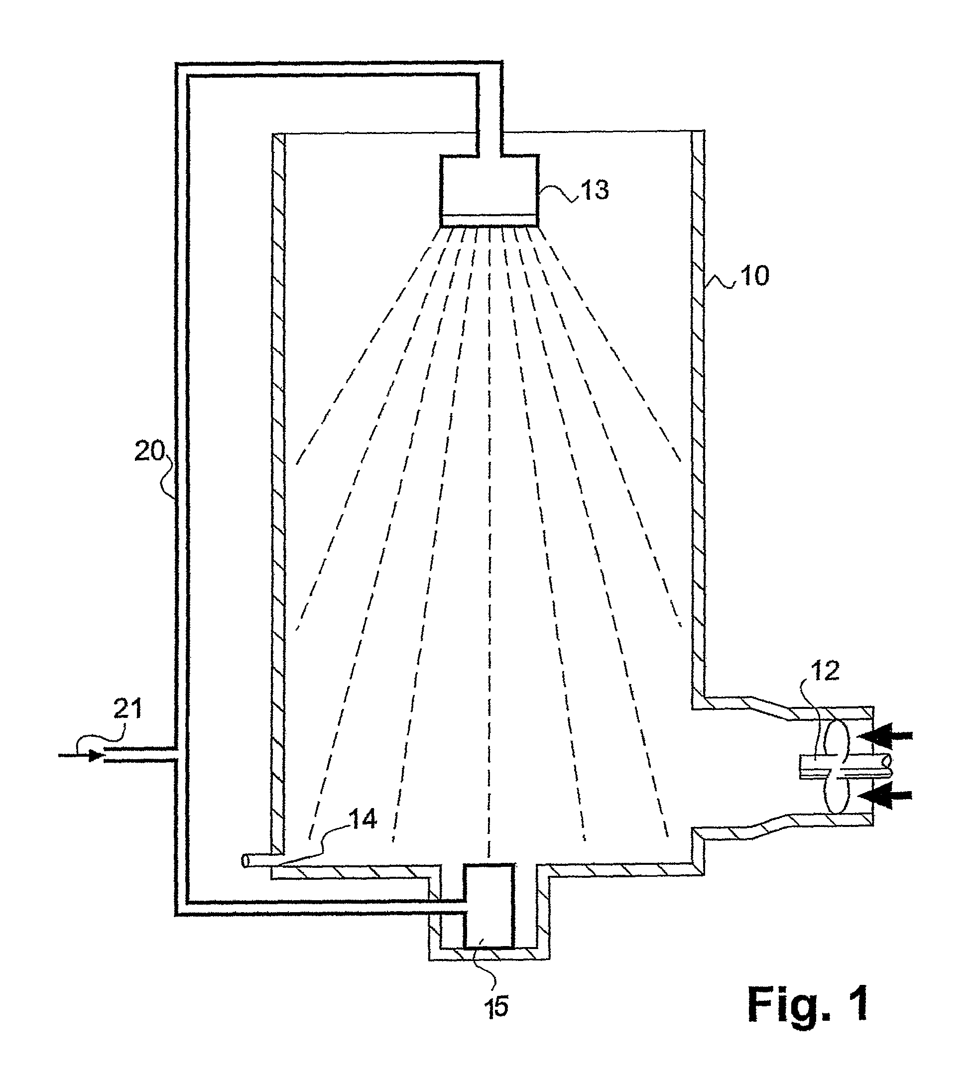
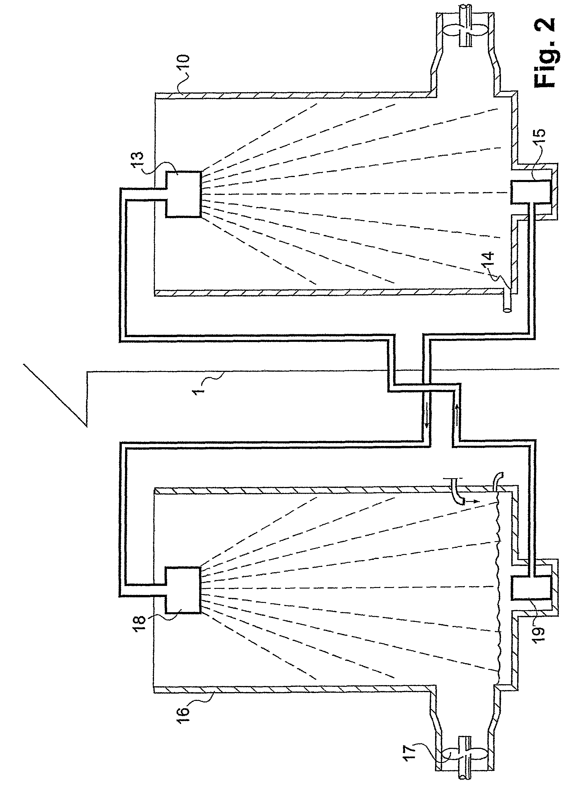
[0035]FIG. 1 presents an embodiment of the invention, wherein there is a condenser 10 in the climate control system of the greenhouse and which explains for example the cooling of the greenhouse according to the invention.

[0036]FIG. 1 has a condenser 10, which here is a spray condenser to the lower end of which warm air from the greenhouse is blown by means of a blower 12, which flows upwards through the condenser 10 and is returned back to the greenhouse. Cold or cool water is lead to the means 13 in the upper end of the condenser, here a sprinkler, fr...


PUM


Abstract

The system is for regulating the climate of the greenhouse. The warm greenhouse air is cooled by cooling water. The system has a spray condenser that includes a conduit for leading the cooling water to the condenser. The condenser has a blower to transfer warm air to be cooled to the condenser. The warm air from the greenhouse is used to warm the water sprayed from the spray condenser. The cooling water may be delivered from an evaporator that has water that is cooled by outside air blown into the evaporator.

Description

PRIOR APPLICATIONS[0001]This is a US national phase patent application that claims priority from PCT / FI2005 / 000520, filed 1 Dec. 2005, that claims priority from Finnish Patent Application. No. 20041572, filed 3 Dec. 2004.TECHNICAL FIELD[0002]This invention comprises a greenhouse, a greenhouse climate control system and a method of controlling greenhouse climate.TECHNICAL BACKGROUND[0003]Previously known greenhouses are those in which the climate is controlled by means of ventilation doors or blowers. In those, excess sun energy and excess moisture are removed from the greenhouse by means of ventilation. In optimal growing conditions, the temperature is ca 18-25° C., the air humidity ca 70-90% and the carbon dioxide concentration more than 1000 ppm. Optimal growing conditions require a good control of the air temperature, moisture and carbon dioxide concentration. It is clear that this can not be reached in an open greenhouse. As the cooling takes place by means of external air in an...

Claims


Application Information

Patent Timeline
Patent Type & Authority Patents(United States)
IPC IPC(8): F25D17/06A01G9/00A01GA01G9/24F24F5/00
CPCA01G9/246F24F5/0035Y02B30/545Y02A40/25Y02B30/54Y02P60/14
Inventor HUHTA-KOIVISTO, ESKOHUTTUNEN, JUKKA
Owner FINN GROWERS OY
Learn More