
Apparatus and method for estimating data relating to a time difference and apparatus and method for calibrating a delay line

a delay line and data estimation technology, applied in the field of signal processing, can solve the problems of uncontrollable device accuracy, non-linearity and even significantly non-monotonic behavior, and inability to fully optimize the measurement accuracy, so as to improve the circuit characteristics, improve the accuracy, and improve the effect of production yield

Active Publication Date: 2014-09-02
ADVANTEST CORP
View PDF11 Cites 3 Cited by
  • Summary
  • Abstract
  • Description
  • Claims
  • Application Information

AI Technical Summary

Benefits of technology

The patent describes a new technology for improving the accuracy and speed of measuring devices. The technology involves using a special kind of delay line that has a high number of stages, but only a small number of these stages contribute to the accuracy of the measurement. The technology also allows for flexibility in design and reduces the cost of manufacturing. By using this technology, devices can be produced with better performance and higher resolution, while also allowing for the use of more complex delay line configurations. Overall, the technology allows for faster and more accurate measurements at a lower cost.

Problems solved by technology

However, unavoidable gate delay mismatches lead to non-linearities and even significantly non-monotonic behavior.
While this concept is advantageous for several applications due to the easy-to-implement and fast-to-implement calibration process, nevertheless, there exists a situation in which the accuracy of the measurements is not fully optimum.
In addition, due to the difference between the stages actually used and actually manufactured stages there exists an uncontrollable accuracy problem of the device, since the accuracy of the device will be poor in regions where there are several “shadowed” stages, and the measurement accuracy will be high in other regions of the device having no or only a small number of shadowed stages.
Since, however, specifications are so that the poorest resolution portion determines the overall resolution specification of the device, producing devices having a very high-resolution specification will result in a high number of devices, which fail the final quality test.
This enhances the cost of the manufacturing process per useful device to a high degree.

Method used


Image

  • Apparatus and method for estimating data relating to a time difference and apparatus and method for calibrating a delay line
  • Apparatus and method for estimating data relating to a time difference and apparatus and method for calibrating a delay line
  • Apparatus and method for estimating data relating to a time difference and apparatus and method for calibrating a delay line

Examples


Embodiment Construction

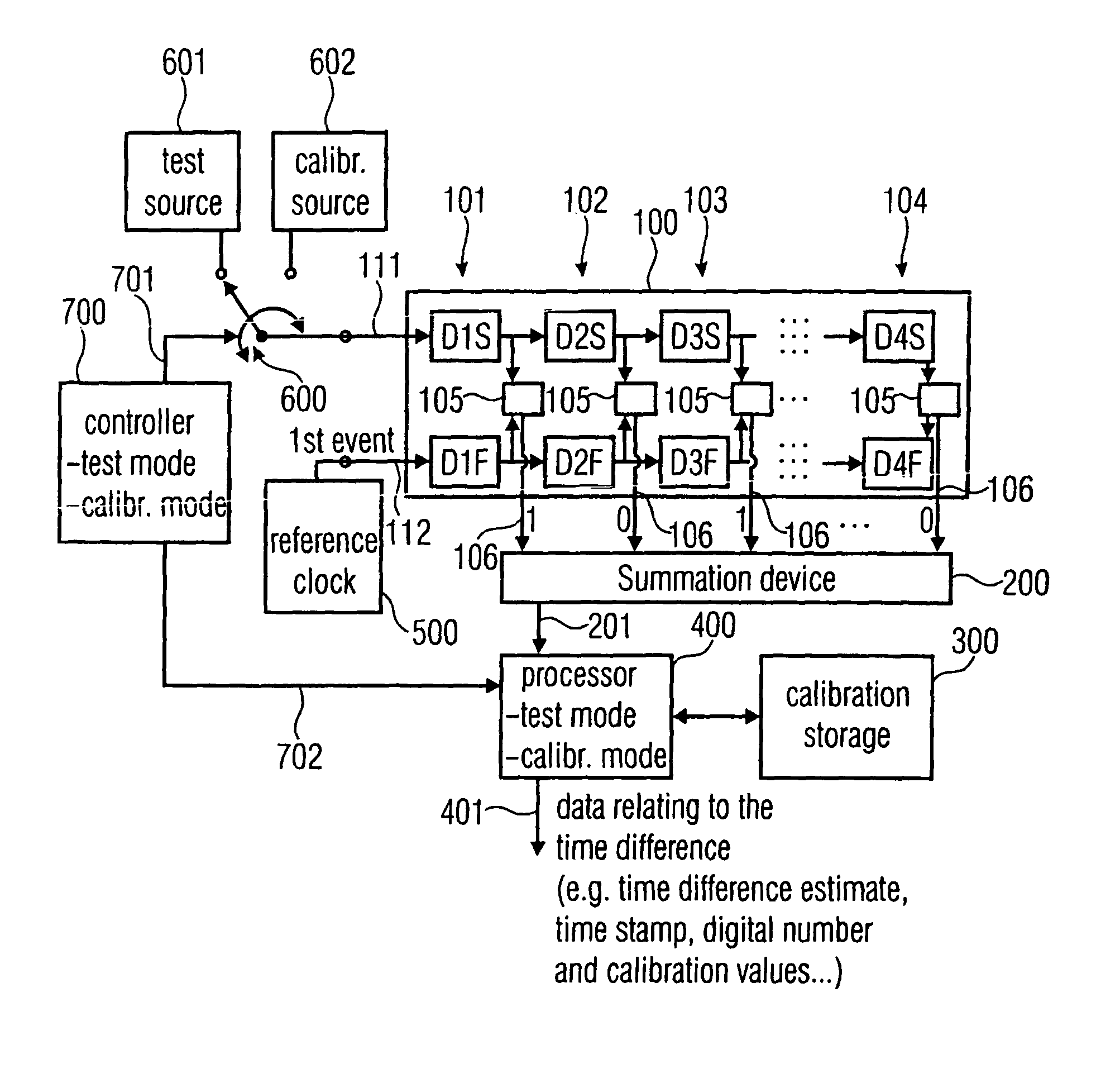
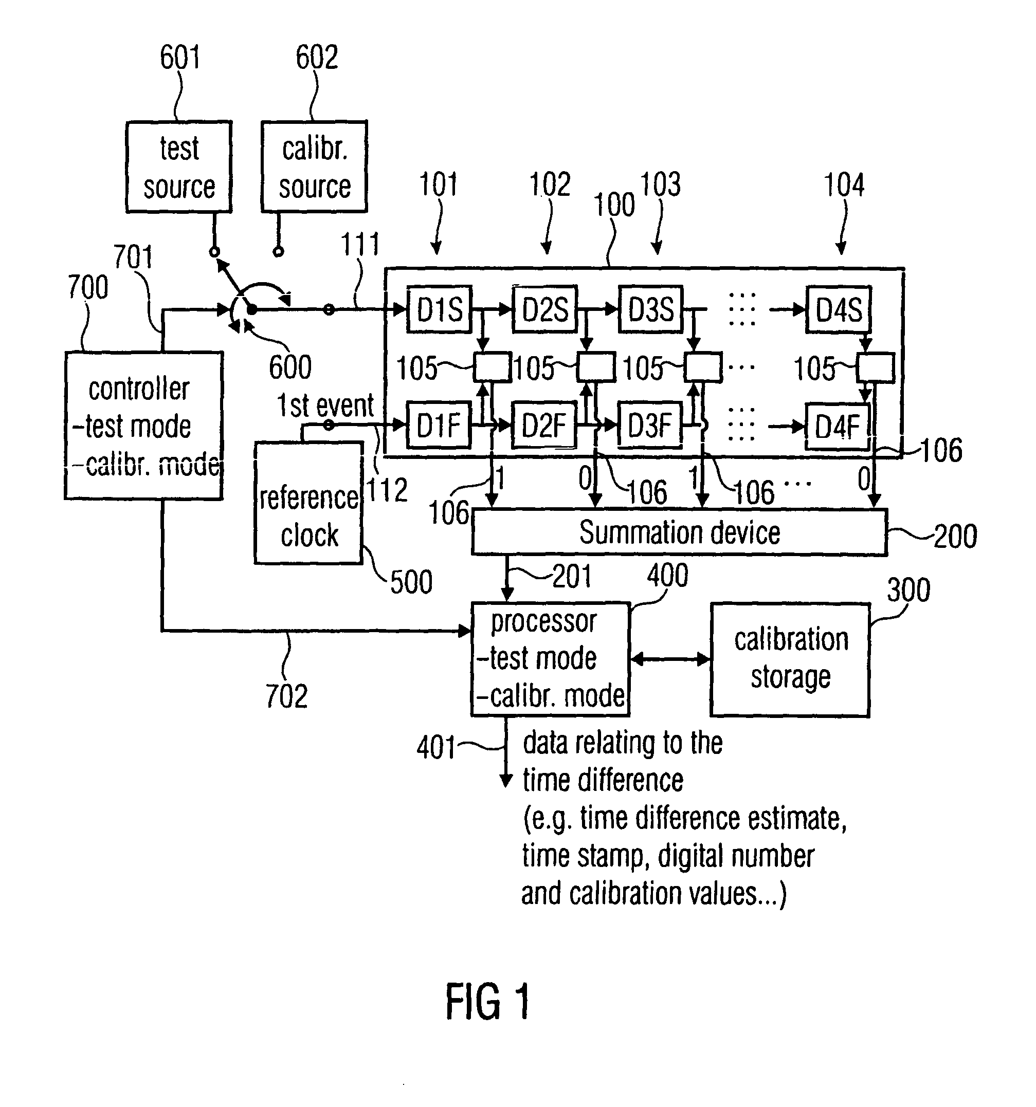
[0048]FIG. 1 illustrates an apparatus for estimating data relating to a time difference between two events. An exemplary time difference between two events is indicated in FIG. 8 where there is a first input into the time to digital converter or, specifically, into a delay line not illustrated in FIG. 8 and in which a second input into the TDC (Delay Line) is indicated as well. The first input is connected to a test signal having a test signal edge indicated as “event” in FIG. 8. The second event is represented by a rising edge of a clock signal connected to the second input (CLK) of the TDC. The test clock has a period of R and the TDC measures the distance t as indicated in FIG. 8. Thus, the complete time stamp output by the TDC in FIG. 8 is equal to N×R−t. Depending on different applications of the present invention, one input into the TCC need not necessarily be a clock, i.e. the reference clock of the automatic test equipment, but the input can also be another test edge when th...


PUM


Abstract

An apparatus for estimating data relating to a time difference between two events includes a delay line having a plurality of stages. Each stage has a delay difference between a first delay in a first part and a second delay in a second part. This delay difference is measured by a phase arbiter in each stage, which outputs an indication signal indicating whether the first event of two events in the first part precedes or succeeds a second event of the two events in the second part. A summation device is provided for summing over the indication signals of the plurality of stages to obtain a sum value. The sum value indicates a time difference estimate.

Description

BACKGROUND OF THE INVENTION[0001]The present invention is related to signal processing and, specifically, to signal measurement devices used in automatic test equipments.[0002]Time-to-digital converters (TDC) in automatic test equipment applications time stamp selected events from the device under test (DUT), i.e. measure the arrival time relative to a tester clock. A time stamper is also known as a continuous time interval analyzer.[0003]Time stamp measurements have a large number of applications in test, each with different requirements. Jitter measurements of high-speed serial interfaces necessitate a high resolution of about 1% of a bit period, i.e. 3 ps at 3 Gbps and can be made using time stamps. The signal may have an arbitrary phase relative to the tester clock. Skew measurements between clock and data of source-synchronous busses necessitate a high resolution of about 1% of bit period combined with a highest possible sample rate to obtain high coverage of sporadic timing vi...

Claims


Application Information

Patent Timeline
Patent Type & Authority Patents(United States)
IPC IPC(8): H03D13/00G04F10/00
CPCG04F10/005H03M1/50H03M1/10
Inventor RIVOIR, JOCHEN
Owner ADVANTEST CORP
Learn More