Electrode support structure assemblies
a technology of support structure and electrode, which is applied in the field of electromechanical support structure assemblies, can solve the problems of limiting, corrals, and difficult for the electrode support structure to collapse evenly, and achieve the effects of less stress, less electrode distribution, and less stress
- Summary
- Abstract
- Description
- Claims
- Application Information
AI Technical Summary
Benefits of technology
Problems solved by technology
Method used
Image
Examples
first embodiment
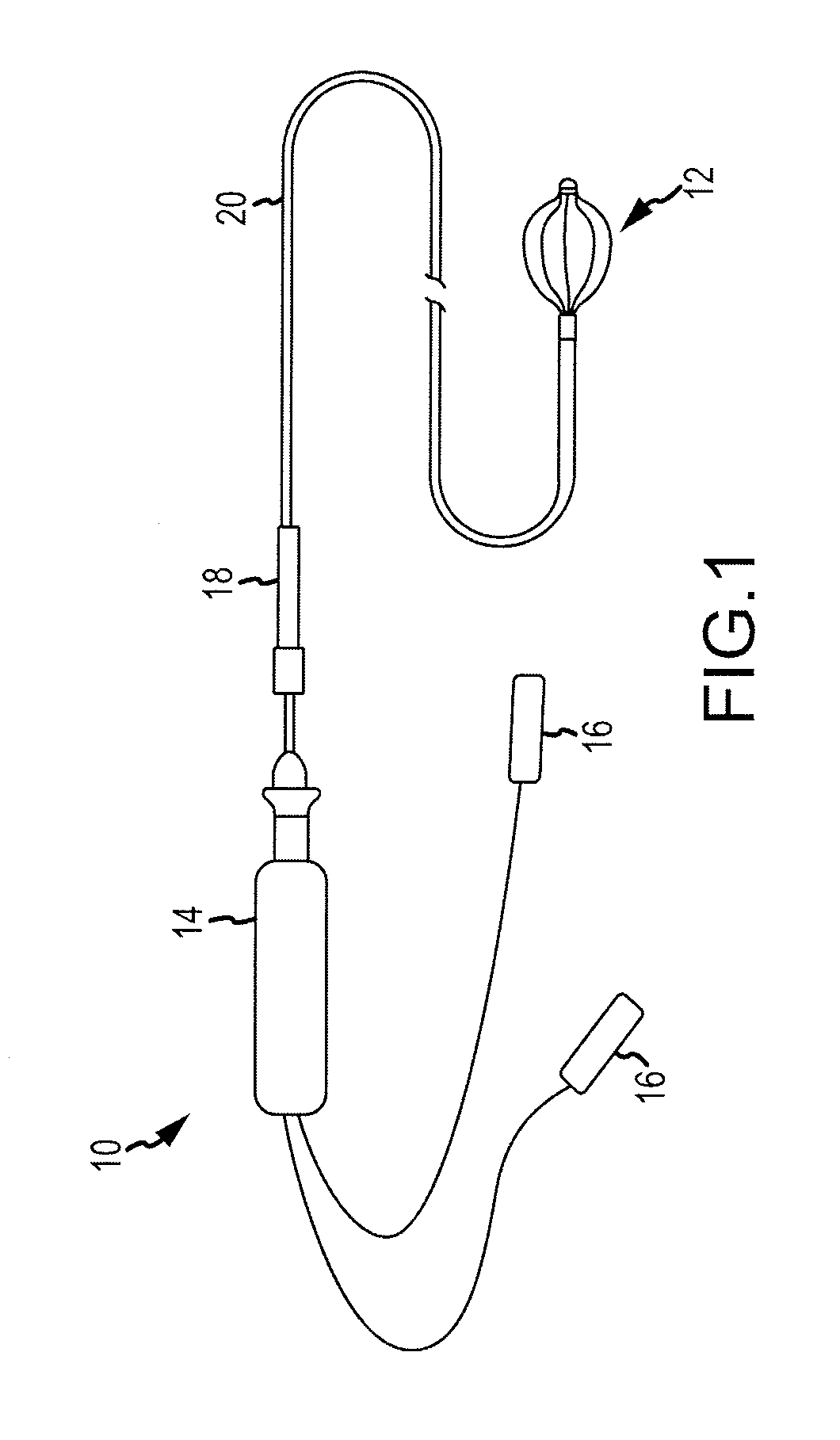
[0036]Referring now to FIG. 1, a side view of an intracardiac catheter system 10 employing an electrode support structure assembly 12 in accordance with the disclosure is generally illustrated. The catheter system 10 includes a handle 14 and connectors 16 disposed proximal to the handle 14 for making electrical connections to a visualization, navigation, and / or mapping system (not shown) such as those systems available under the name ENSITE NAVX™ (aka ENSITE™ Classic as well as newer versions of the ENSITE™ system, denoted as ENSITE VELOCITY™) and available from St. Jude Medical, Inc. The handle 14 can have a uni-directional design, a bi-directional design, or any other suitable design and be accordingly configured to steer the electrode support structure assembly 12. The catheter system 10 can also include an introducer 18 located distally of the handle 14 that may be used to deliver an elongated catheter body 20 into the body of a patient, through a hemostasis valve of another, lo...
second embodiment
[0046]Referring now to FIGS. 4-9, an electrode support structure assembly 112 in accordance with the disclosure is generally illustrated. The electrode support structure assembly 112 can be similarly mounted to the distal end of the elongated catheter body 20 (see FIG. 1) and can be substantially identical to electrode support structure assembly 12 described above except for differences in the proximal end portion of each of the plurality of splines and differences in the elements configured to join the distal end portions of the splines as described hereinbelow. The electrode support structure assembly 112 can further comprise one or more electrodes (such as electrodes 54 shown in FIG. 2) supported by one or more of the plurality of splines 124. For example, one or more of the plurality of splines 124 can have one or more electrodes (such as electrodes 54 shown in FIG. 2) mounted on the non-conductive covering of each of the plurality of splines 124 in accordance with various embod...
third embodiment
[0055]In accordance with the disclosure, each spline 241, 1241, may be symmetric with each adjacent spline 242, 1242. In other words, each spline 241, 1241, 242, 1242 can have the same electrode layout when flipped proximal end to distal end. In accordance with such an arrangement, a first distance dist1 between a distal-most electrode 54d of the first plurality of electrodes 541 and a distal end 281 of the first spline 241, 1241 is substantially the same as a second distance dist2 between a proximal-most electrode 54p of the second plurality of electrodes 542 and a proximal end 262 of the second spline 242, 1242. Although these particular electrode arrangements are mentioned and illustrated in detail, there may be additional electrode arrangements that be utilized in accordance with various embodiments of the disclosure. For example and without limitation, spacing between electrodes 54 can vary based on the length of splines 241, 1241, 242, 1242 or the desired distance from the pro...
PUM
 Abstract
Description
Claims
Application Information
 - R&D
- Intellectual Property
- Life Sciences
- Materials
- Tech Scout
- Unparalleled Data Quality
- Higher Quality Content
- 60% Fewer Hallucinations
Browse by: Latest US Patents, China's latest patents, Technical Efficacy Thesaurus, Application Domain, Technology Topic, Popular Technical Reports.
© 2025 PatSnap. All rights reserved.Legal|Privacy policy|Modern Slavery Act Transparency Statement|Sitemap|About US| Contact US: help@patsnap.com


