
System for making a bone repair

a bone repair and bone plate technology, applied in the field of bone repair systems, can solve the problems of affecting the repair effect, requiring a fairly invasive process, and unable to fix dorsally displaced bone fragments using bone plates, etc., and achieves high stability, effective bone repair, and high stability. the effect of structur

Active Publication Date: 2014-09-02
SWISS ORTHO
View PDF25 Cites 17 Cited by
  • Summary
  • Abstract
  • Description
  • Claims
  • Application Information

AI Technical Summary

Benefits of technology

This method achieves high stability in bone fracture repair with fewer screws required, minimizing soft tissue dissection and effectively managing complex fractures by creating a rigid structure that does not rely on direct bone anchoring, suitable for severe and comminuted fractures.

Problems solved by technology

In contrast, bone plates are internal devices that mount directly to bone to span and support the fracture and require a fairly invasive process for placement and installation thereof.
Unfortunately, internal fixation of such dorsally displaced bone fragments using bone plates has proved problematic.
However, unless the bone plate has a very low profile, dorsal tendons overlying the bone plate may rub against it, producing tendon irritation or even tendon rupture.
However, while volar fixation provides advantages as compared to dorsal fixation, there are settings where a single volar or dorsal implant does not provide enough stability to provide reliable support for the bony structures.
This is particularly problematic in elderly patients that generally have poor quality bone or in high-speed injuries with highly comminuted fracture patterns.
The difficulty is that when the screws are installed into the distal radius, they may not find sufficient bone structure to hold distal bone fragments in position against the bone plate.

Method used


Image

  • System for making a bone repair
  • System for making a bone repair
  • System for making a bone repair

Examples


Embodiment Construction

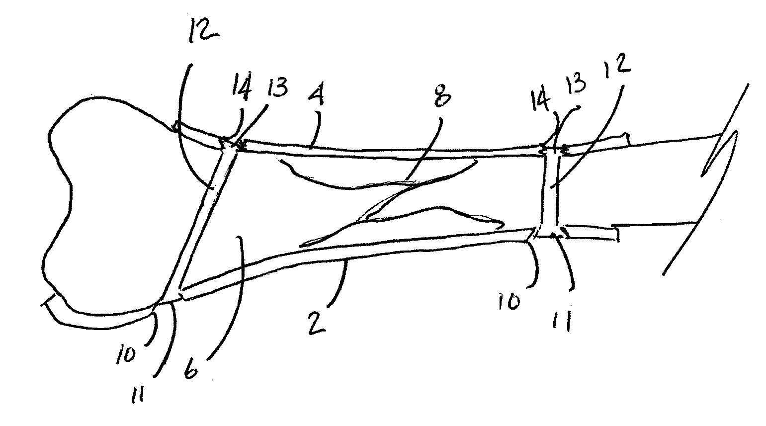
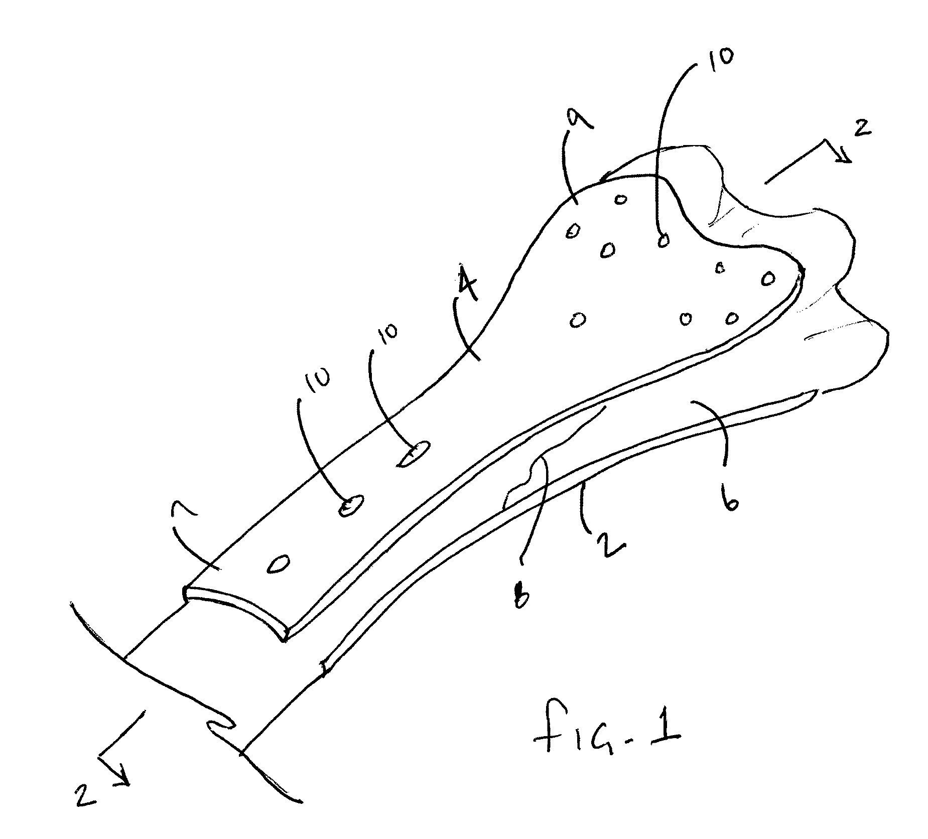
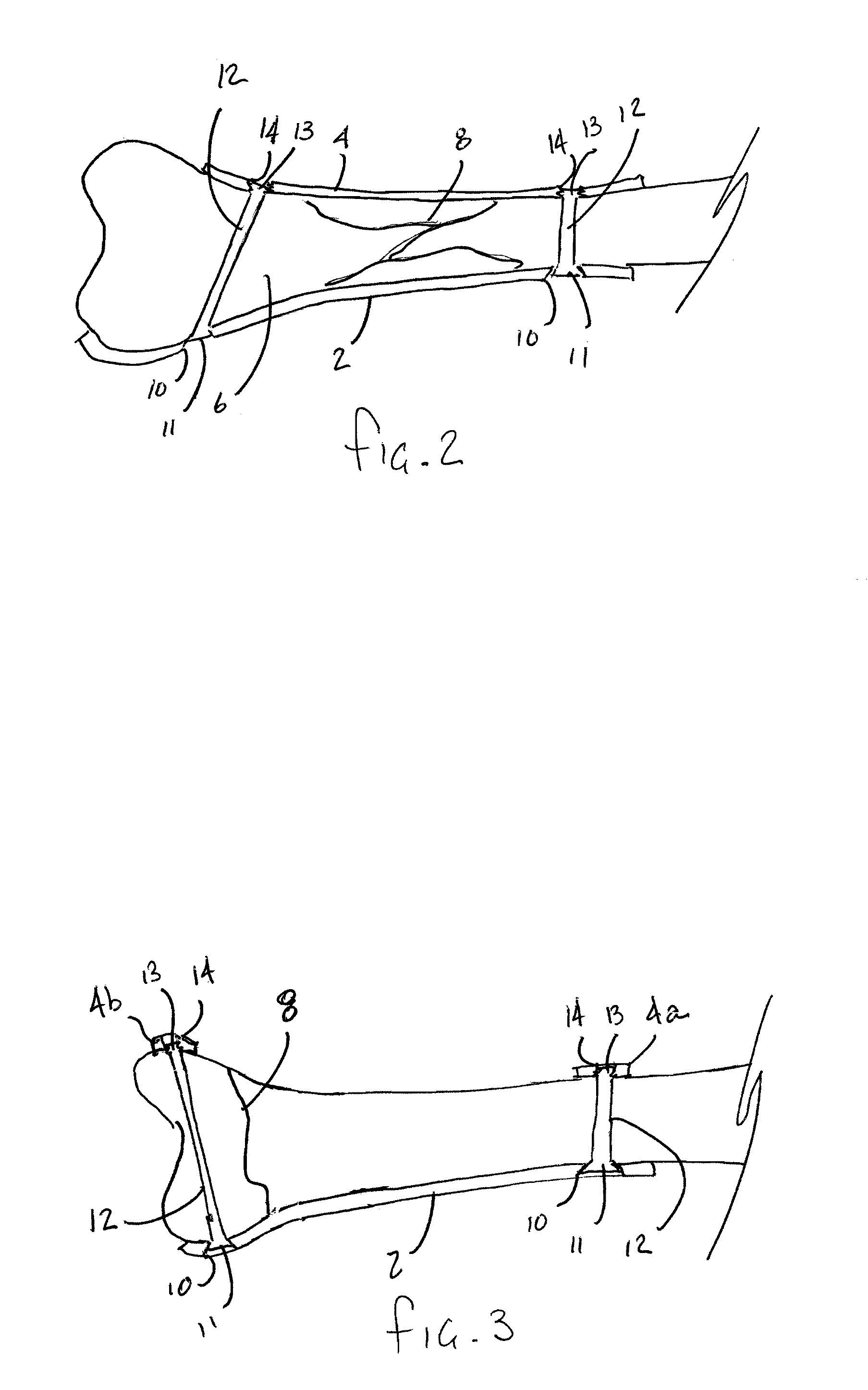
[0021]Now referring to the drawings, the bone repair system of the present invention is shown and generally illustrated at FIGS. 1-5 while the method of the present invention is depicted at FIG. 6. Generally, the present invention is directed to a bone repair system that employs two complimentary opposing plates to buttress a fracture from both sides of a bone. In one example, in a repair involving a wrist fracture, the plates are affixed to one another using screws that are installed from a volar plate, through the bone and into the dorsal plate. The use of these complimentary volar and dorsal plates creates a highly stable repair structure while requiring fewer screws thereby minimizing the degree of soft tissue dissection.

[0022]Turning now to FIG. 1, in the preferred embodiment of the present invention two complimentary opposing bone plates 2, 4 are employed on opposing sides of the bone 6 having the fracture 8 to be buttressed. While the bone 6 to be repaired as depicted in FIG....


PUM


Abstract

A method and system is provided for repairing bone fractures at locations where high levels of stability are required. The system employs two plates to buttress a fracture from both the dorsal and volar sides. The plates are affixed to one another using screws that are installed from a volar plate, through the bone and into a dorsal plate. The method provides for use of a directional guide that allows the precise placement of Kirschner wires for temporary fixation of the fracture, installation of a first bone fixation plate using the installed K-wires for alignment, installation of a second bone plate adjacent the bone to be repaired and opposite the first bone plate, and installation of cannulated fasteners between the two opposing bone plates such that the fasteners rigidly engage both of the bone plates.

Description

CROSS-REFERENCE TO RELATED APPLICATIONS[0001]This application is related to and claims priority from earlier filed U.S. Provisional Patent Application No. 60 / 972,029, filed Sep. 13, 2007.BACKGROUND OF THE INVENTION[0002]The present invention relates generally to a method and system for use in the positive and secure positioning of fractured bones. More specifically, the present invention relates to double plate assembly for use in repairing bone fractures that demonstrates improved stability when buttressing fractures that exhibit complex articular patterns and comminution.[0003]The human skeleton consists of 206 individual bones that cooperate to perform a variety of important functions such as support, movement, protection, storage of minerals, and formation of blood cells. The bones within the skeleton are generally grouped into two categories, the axial skeleton and the appendicular skeleton. The axial skeleton includes 80 bones that make up the body's center of gravity and the ...

Claims


Application Information

Patent Timeline
Patent Type & Authority Patents(United States)
IPC IPC(8): A61F2/42A61B17/17A61B17/68A61B17/80
CPCA61B17/683A61B17/8061A61B2017/1782A61B17/1728A61B17/864A61B17/8635A61B17/8014A61B17/848A61B17/8057A61B17/1782
Inventor DASILVA, MANUEL
Owner SWISS ORTHO
Learn More