
Medium voltage variable frequency driving system

a technology of variable frequency and driving system, applied in the direction of motor control for motor oscillation damping, dynamo-electric converter control, etc., can solve the problems of high cost and complexity, system structure is relatively complex, limited application of traditional direct current (dc) speed regulating technology adopted in a conventional motor machine, etc., to reduce reduce the cost, and reduce the effect of the number of switch elements

Active Publication Date: 2014-08-19
DELTA ELECTRONICS (SHANGHAI) CO LTD
View PDF13 Cites 18 Cited by
  • Summary
  • Abstract
  • Description
  • Claims
  • Application Information

AI Technical Summary

Benefits of technology

This configuration decreases the number of switch elements by at least half, lowers the requirements for diode recovery characteristics, and reduces costs by eliminating the need for high-frequency commutation, resulting in a simpler and more reliable control system for driving induction motors in applications like wind generators and pumps.

Problems solved by technology

In the controlling of a motor machine or an induction motor, it is an important issue to adjust the motor speed.
The traditional direct current (DC) speed regulating technology adopted in a conventional motor machine has limited applications due to big volume and high failure rate of hardware.
However, the multistage transformer arranged in the above mentioned conventional medium-voltage variable frequency speed-regulating system is of large volume and high weight, which leads to high cost and complex design.
Thus, it is an important researching issue regarding how to use other speed-regulating system structures to omit the arrangement of the transformer while achieving the same performance.
However, the above mentioned conventional medium-voltage variable frequency speed-regulating system without a transformer is still provided with a large number of switch elements, and the system has a relatively complex structure and still high cost.

Method used


Image

  • Medium voltage variable frequency driving system
  • Medium voltage variable frequency driving system
  • Medium voltage variable frequency driving system

Examples


Embodiment Construction

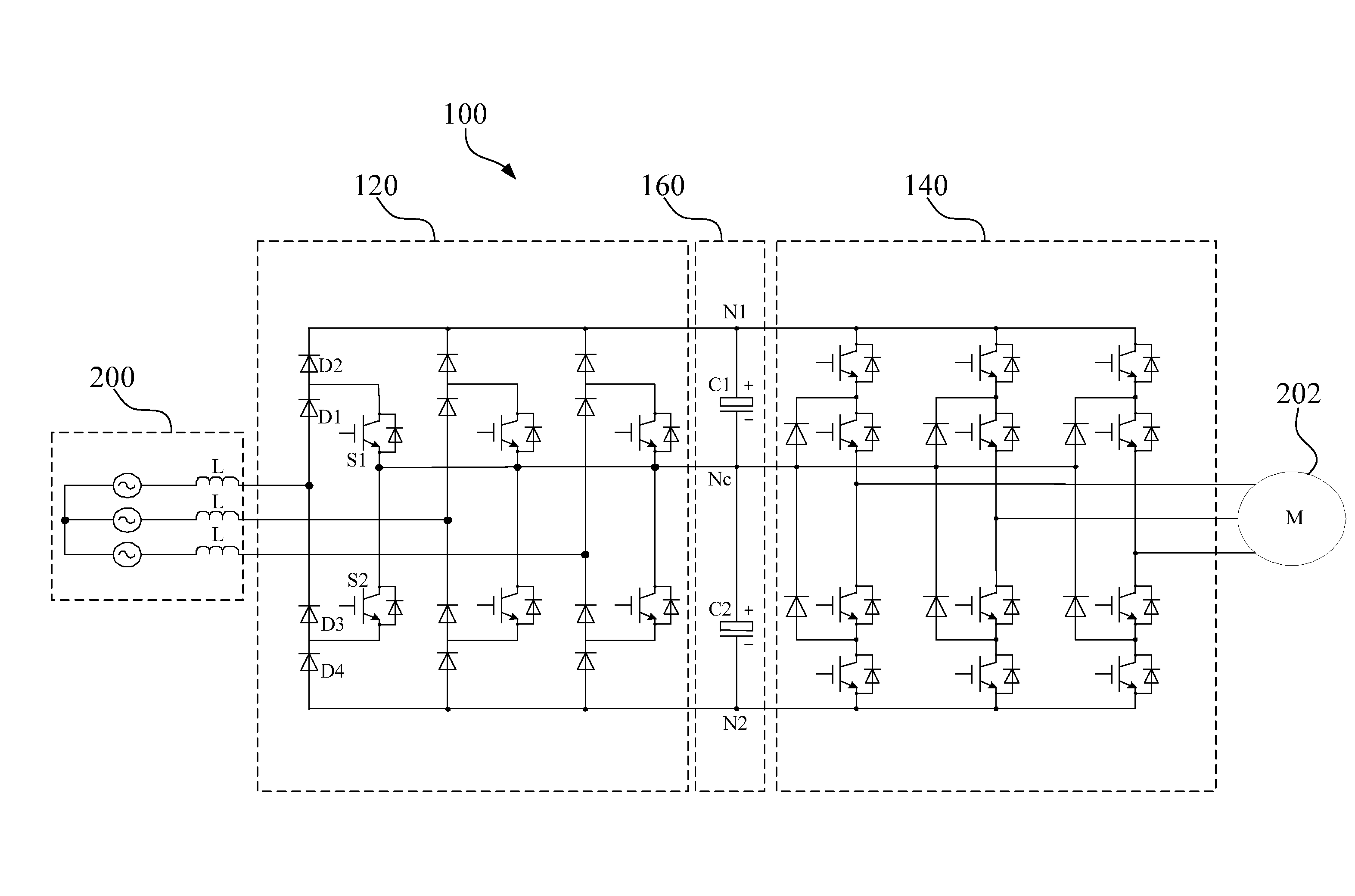
[0043]Referring to FIG. 4, FIG. 4 illustrates a schematic functional block diagram of a medium voltage variable frequency driving system 100 according to an embodiment of the present invention. In this embodiment, the medium voltage variable frequency driving system 100 is coupled with a three-phase electrical grid 200, for driving an induction motor 202. As shown in FIG. 4, the medium voltage variable frequency driving system 100 includes a three-phase switch-mode rectification module 120, a multilevel inverter 140 and a high-capacity capacitor module 160. Referring to FIG. 5 at the same time, FIG. 5 illustrates a schematic circuit diagram of the three-phase switch-mode rectification module 120, the multilevel inverter 140 and the high-capacity capacitor module 160 in the medium voltage variable frequency driving system 100 of FIG. 4.

[0044]As shown in FIGS. 4 and 5, the three-phase switch-mode rectification module 120 is coupled with the three-phase electrical grid 200, for convert...


PUM


Abstract

The present invention provides a medium voltage variable frequency driving system, including a three-phase switch-mode rectification module, a multilevel inverter and a high-capacity capacitor module. The three-phase switch-mode rectification module is coupled with a three-phase electrical grid, for converting an AC voltage input with a fixed operating frequency on the three-phase electrical grid into a DC voltage. The multilevel inverter is used for converting the DC voltage into an AC voltage with a required variable frequency, so as to drive an induction motor. The high-capacity capacitor module is coupled between the three-phase switch-mode rectification module and the multilevel inverter, for temporarily storing the DC voltage. In the present invention, a three-phase switch-mode rectification technology is used at the front-end rectifier, and a diode-clamped three-level inverter is adapted correspondingly at the rear-end inverter.

Description

RELATED APPLICATIONS[0001]This application claims priority to Chinese Application Serial Number 201110269272.8, filed Sep. 13, 2011, which is herein incorporated by reference.BACKGROUND[0002]1. Field of Invention[0003]The present invention relates to a variable frequency drive system. More particularly, the present invention relates to a three-phase medium voltage variable frequency driving system.[0004]2. Description of Related Art[0005]In the controlling of a motor machine or an induction motor, it is an important issue to adjust the motor speed. The traditional direct current (DC) speed regulating technology adopted in a conventional motor machine has limited applications due to big volume and high failure rate of hardware.[0006]A variable-frequency drive (VFD) is an electric drive element using the variable-frequency technology and the electronic technology to control an alternating current (AC) motor by changing the frequency and amplitude of a motor operation power supply.[000...

Claims


Application Information

Patent Timeline
Patent Type & Authority Patents(United States)
IPC IPC(8): H02P23/04H02P27/14
CPCH02P27/14H02M7/487H02M5/4585
Inventor ZHANG, YICHEN, WEIPU, BO-YU
Owner DELTA ELECTRONICS (SHANGHAI) CO LTD
Learn More