
Electronic measuring device and method of converting serial data to parallel data for storage using the same

a technology of parallel data and measuring device, which is applied in the direction of data conversion, digital variable/waveform display, instruments, etc., can solve the problem of limited storage capacity of serial-parallel shifter, achieve accurate and effective data structure, increase memory use efficiency, and increase storage speed and processing efficiency

Inactive Publication Date: 2014-08-12
ZEROPLUS TECH CO LTD
View PDF11 Cites 4 Cited by
  • Summary
  • Abstract
  • Description
  • Claims
  • Application Information

AI Technical Summary

Benefits of technology

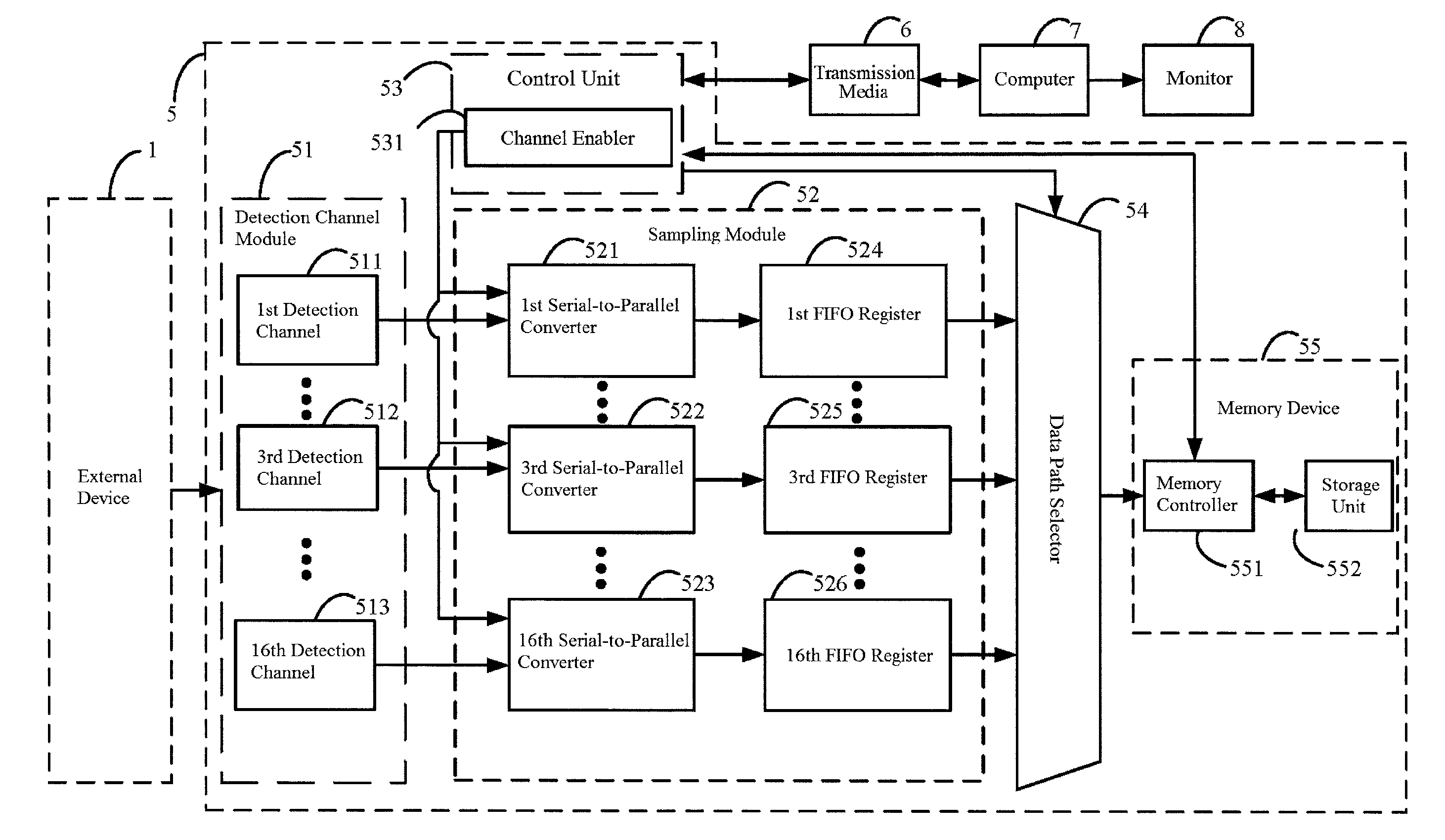
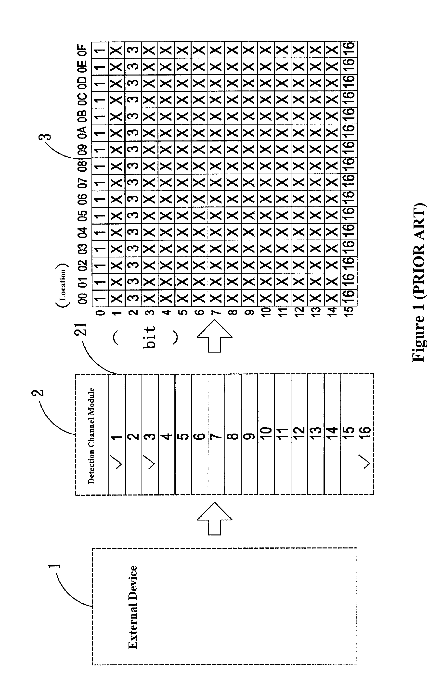
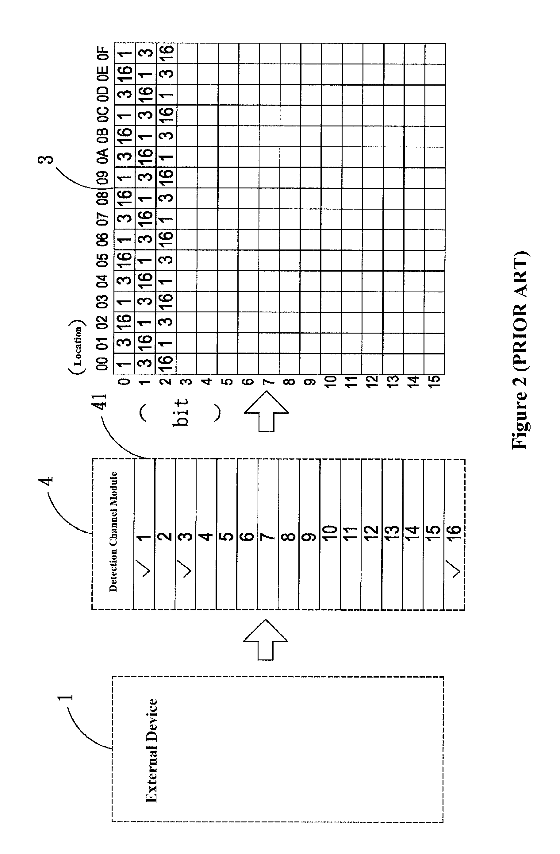
[0012]The present invention provides a user to selectively enable only the needed detection channels. The user will be able to use the enabled channels to receive signals from the external device and output serial data to the sampling module. The data path selector stores the parallel data into the memory device in an efficient manner. The innovative serial-to-parallel data conversion method creates an accurate and effective data structure for storage purpose. The conversion method also solves the problem that when the number of detections channels is different from the length of the storage unit, data will be split and stored in different location.
[0013]Additionally, the innovated storage method increases memory use efficiency. With the indicators in the storage unit, there is no more need to determine where the data needs to be stored when every time data is transferred to the storage unit. Without the indicators, data reading becomes increasingly complicated and requires a large amount of computing resources. For these reasons, this invention will increase the storage speed and processing efficiency.

Problems solved by technology

The serial-parallel shifter has limited storage capacity.

Method used


Image

  • Electronic measuring device and method of converting serial data to parallel data for storage using the same
  • Electronic measuring device and method of converting serial data to parallel data for storage using the same
  • Electronic measuring device and method of converting serial data to parallel data for storage using the same

Examples


Embodiment Construction

[0023]The detailed description and technical contents of the present invention will be explained with reference to the accompanying drawings. However, the drawings are illustrative only but not used to limit the present invention.

[0024]FIG. 3 is a block diagram of an embodiment according to the present invention. The block diagram shows the major components of the invention. As shown in FIG. 3, the electronic measuring device 5 is connected to an external device 1. The external device 1 sends electronic signal to the electronic measuring device 5 allowing a user to use the electronic measuring device 5 to conduct electronic measuring through the external device 1. The data collected by the electronic measuring device 5 can be transmitted to a computer 7 through a transmission interface 6. A monitor 8 is connected to the computer 7 to display the data to the user.

[0025]In this embodiment, the electronic measuring device 5 is a logic analyzer. Its main utility is to detect electronic ...


PUM


Abstract

An electronic measuring device includes a detection channel module, a sampling module, a control unit, a data path selector and a memory device. A user will be able to selectively enable the desired detection channels and store only data collected from enabled channels. The data collected from the detection channels are in serial data form. The device utilizes a serial-parallel shifter in its sampling module to convert the serial data to parallel data bytes. Two indicators in the storage unit of the memory device allow users to effectively store the parallel data bytes in designated locations. The innovative data conversion and storage methods of this invention will significantly conserve memory space that otherwise will be occupied by data from the disabled channels and allow accurate and efficient reading of the stored data.

Description

BACKGROUND OF THE INVENTION[0001]1. Field of the Invention[0002]The present invention relates to an electronic measuring device, a method of converting serial data to parallel data Bytes and a method to store the parallel data bytes. Particularly, the electronic measuring device is capable of conducting data analysis on sample data collected from its detection channels, storing the data efficiently in its memory and accurately reading the stored data.[0003]2. Related Prior Arts[0004]In an ever increasing digitalization of today's electronic products, the traditional oscilloscope is no longer capable of detecting signals from more than 8 to 16 channels. Although the in-circuit emulator (ICE) can solve many problems relating to digitalization, the actual time sequence problems still cannot be dealt by software-based in-circuit emulator. Additionally, ICE typically requires specialized computer systems specially designed for the software. As a result, a logic analyzer has become one of...

Claims


Application Information

Patent Timeline
Patent Type & Authority Patents(United States)
IPC IPC(8): G06F3/00G01R13/00G06F5/00G06F13/12G06F13/28G11C29/56
CPCG01R13/00G11C29/56G11C2029/5606G06F13/4027
Inventor CHENG, CHIU-HAO
Owner ZEROPLUS TECH CO LTD
Learn More