
System and method for thermally controlling an electronic display with reduced noise emissions

a technology of electronic display and noise emission, applied in the field of cooling systems, can solve the problems of increasing the difficulty of cooling the internal display components, increasing the cost of cooling,

Active Publication Date: 2014-08-12
MFG RESOURCES INT INC
View PDF26 Cites 62 Cited by
  • Summary
  • Abstract
  • Description
  • Claims
  • Application Information

AI Technical Summary

Benefits of technology

The patent describes a cooling system for electronic display using a combination of circulating gas and ambient gas. The circulating gas removes heat from the front and internal electronic assemblies, while the ambient gas cools the display from the edges. To reduce noise, fans are placed within the heat exchanger or manifold to collect and distribute the ambient gas. The system uses a single fan or two fans to drive the ambient gas through both the heat exchanger and behind the display. The manifolds allow for even cooling and reduce hot spots within the display. Overall, the system ensures efficient cooling and reduced noise for electronic displays.

Problems solved by technology

When surrounding temperatures rise, the cooling of the internal display components can become even more difficult.
In order to produce this level of brightness, illumination devices and electronic displays may produce a relatively large amount of heat.
Still further, in some situations radiative heat transfer from the sun through a front display surface can also become a source of heat.
Furthermore, the market is demanding larger screen sizes for displays.
However, previous designs for moving the gas through the display have been found to generate an undesirable amount of noise emission from the display as well as thermal gradients where portions of the display were cooled but others remained warm.

Method used


Image

  • System and method for thermally controlling an electronic display with reduced noise emissions
  • System and method for thermally controlling an electronic display with reduced noise emissions
  • System and method for thermally controlling an electronic display with reduced noise emissions

Examples


Embodiment Construction

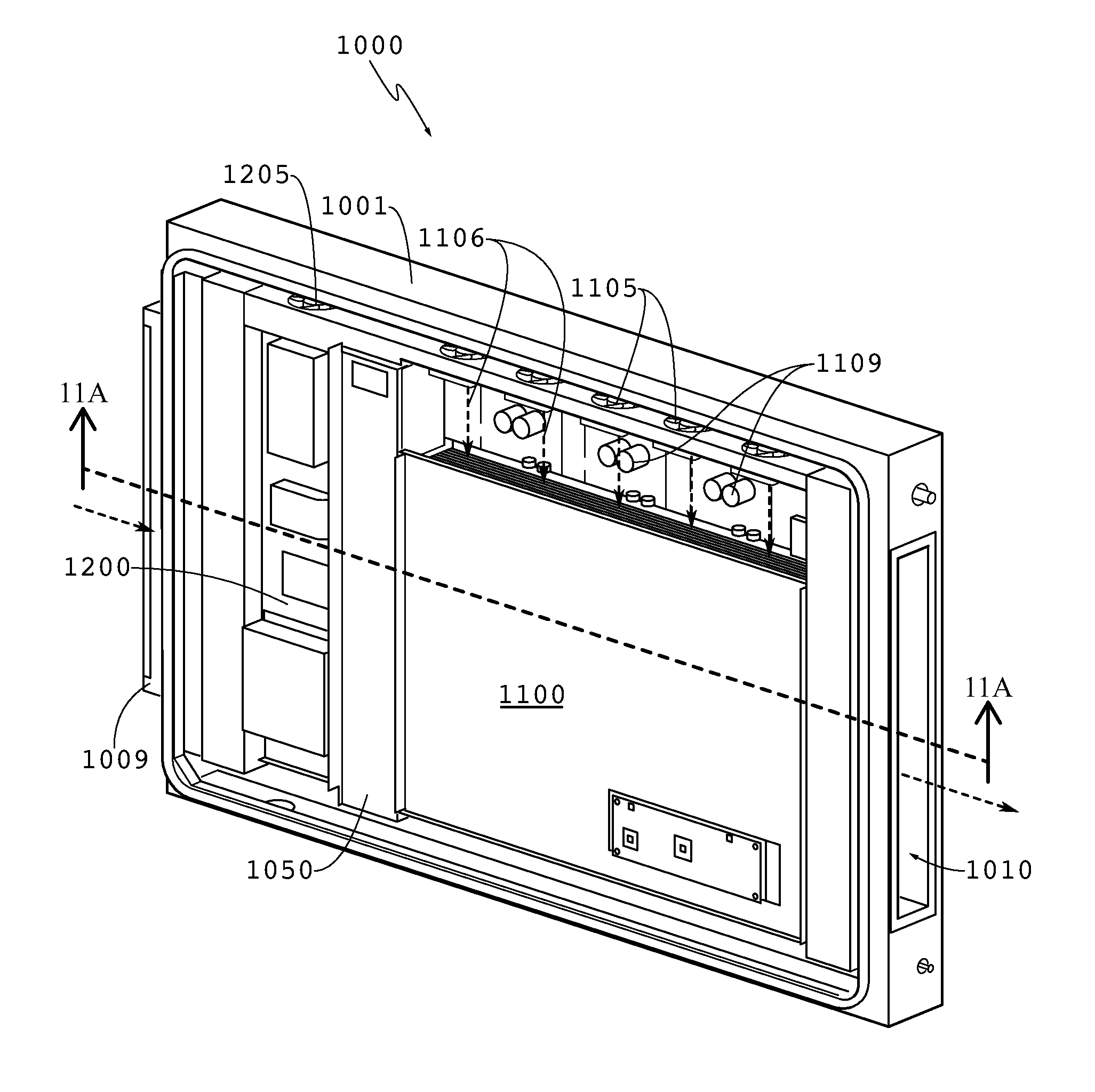
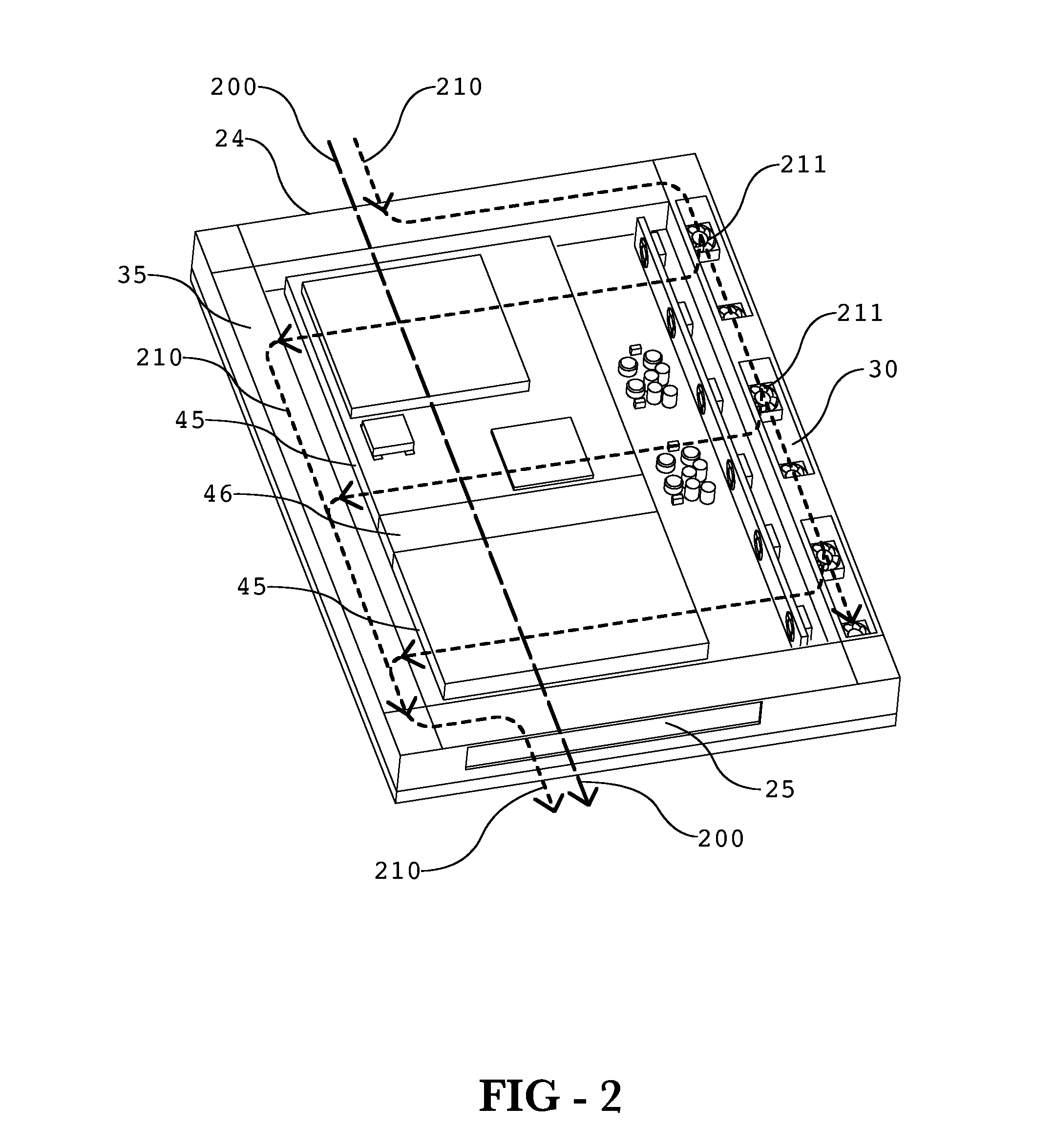
[0008]Exemplary embodiments may use a combination of circulating gas and ambient gas in order to adequately cool an electronic display. Circulating gas may be used to remove heat from the front of the image assembly. Circulating gas may also be used to remove heat from internal electronic assemblies. When using a LCD as the electronic image assembly, circulating gas may also be used to remove heat from the backlight cavity of the LCD. Because the gas is only circulating within the display, it can remain free of particulate and contaminates and will not harm the display.

[0009]Ambient gas may be ingested into the display in order to cool the circulating gas. The ambient gas and the circulating gas may be drawn through a heat exchanger which will allow the heat to transfer from the circulating gas to the ambient gas, preferably without letting the ambient and circulating gases mix with one another. An exemplary embodiment would use a cross-flow heat exchanger. An additional flow of amb...


PUM

PropertyMeasurementUnit
transparentaaaaaaaaaa
forceaaaaaaaaaa
conductiveaaaaaaaaaa

Abstract

An assembly for cooling an electronic image assembly having a rear channel placed behind the image assembly and a heat exchanger for accepting ambient air. The system contains a first fan placed within the heat exchanger to force ambient air through the heat exchanger and the rear channel. A second fan may be used to force circulating gas through an interior portion of the display housing and through the heat exchanger in order to transfer heat to the ingested ambient air.

Description

CROSS-REFERENCE TO RELATED APPLICATIONS[0001]This application claims priority to U.S. Application No. 61 / 375,470 filed on Aug. 20, 2010, herein incorporated by reference in its entirety. This application is a continuation-in-part of U.S. application Ser. No. 13 / 100,580 filed on May 4, 2011, herein incorporated by reference in its entirety. This application is also a continuation-in-part of U.S. application Ser. No. 13 / 100,556 filed on May 4, 2011, herein incorporated by reference in its entirety. This application is also a continuation-in-part of U.S. application Ser. No. 12 / 905,704 filed on Oct. 15, 2010, herein incorporated by reference in its entirety.TECHNICAL FIELD[0002]Exemplary embodiments generally relate to cooling systems and in particular to cooling systems for electronic displays.BACKGROUND OF THE ART[0003]Improvements to electronic displays now allow them to be used in outdoor environments for informational, advertising, or entertainment purposes. While displays of the ...

Claims


Application Information

Patent Timeline
Patent Type & Authority Patents(United States)
IPC IPC(8): H05K7/20G02F1/1333
CPCG02F1/133385F28F3/08H05K7/20972F21V29/22F28D9/0062F21V29/02G02F2001/133628F21V29/70G02F1/133628G09F9/00H10K59/00
Inventor DUNN, WILLIAMHUBBARD, TIMBEDELL, WARE
Owner MFG RESOURCES INT INC
Learn More