
Double-axis rotation rate sensor

a technology of rotation rate sensor and double axis, which is applied in the direction of acceleration measurement using interia force, turn-sensitive devices, instruments, etc., can solve the problems of limited yaw rate, limited yaw movement of the vehicle and therefore the actual yaw rate, and the relatively large number of accidents involving only one motor vehicle, etc., to achieve more precise and/or robust detection, and relatively compact design of the rotation rate sensor

Active Publication Date: 2014-08-05
CONTINENTAL TEVES AG & CO OHG
View PDF10 Cites 20 Cited by
  • Summary
  • Abstract
  • Description
  • Claims
  • Application Information

AI Technical Summary

Benefits of technology

The invention is a sensor that can detect rotation rates on multiple sensitive axes with greater accuracy and robustness, and is also compact. A coupling beam is suspended from a spring, which is attached to a substrate to prevent any movement in the direction of the beam. Overall, the invention improves the detection of rotation rates.

Problems solved by technology

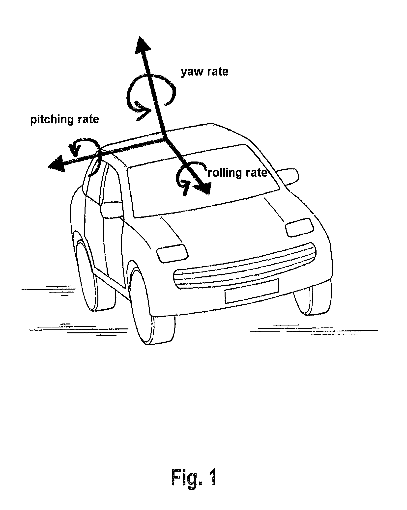
If the actual value of the yaw rate differs from the calculated setpoint value of the yaw rate beyond a predetermined degree at which the driving stability is endangered, the yaw movement of the vehicle and therefore the actual yaw rate are limited to permissible values by selective intervention in the brakes and the engine.
A considerable number of accidents involve only one motor vehicle.
Fatal, injuries usually occur in this type of accident if the motor vehicle rolls over about its longitudinal axis during the accident.
In particular in the case of convertibles, rolling over of the vehicle can have fatal consequences.
However, in the case of convertibles the esthetic impression is adversely affected to a considerable degree by a fixed rollover bar.

Method used


Image

  • Double-axis rotation rate sensor
  • Double-axis rotation rate sensor
  • Double-axis rotation rate sensor

Examples


Embodiment Construction

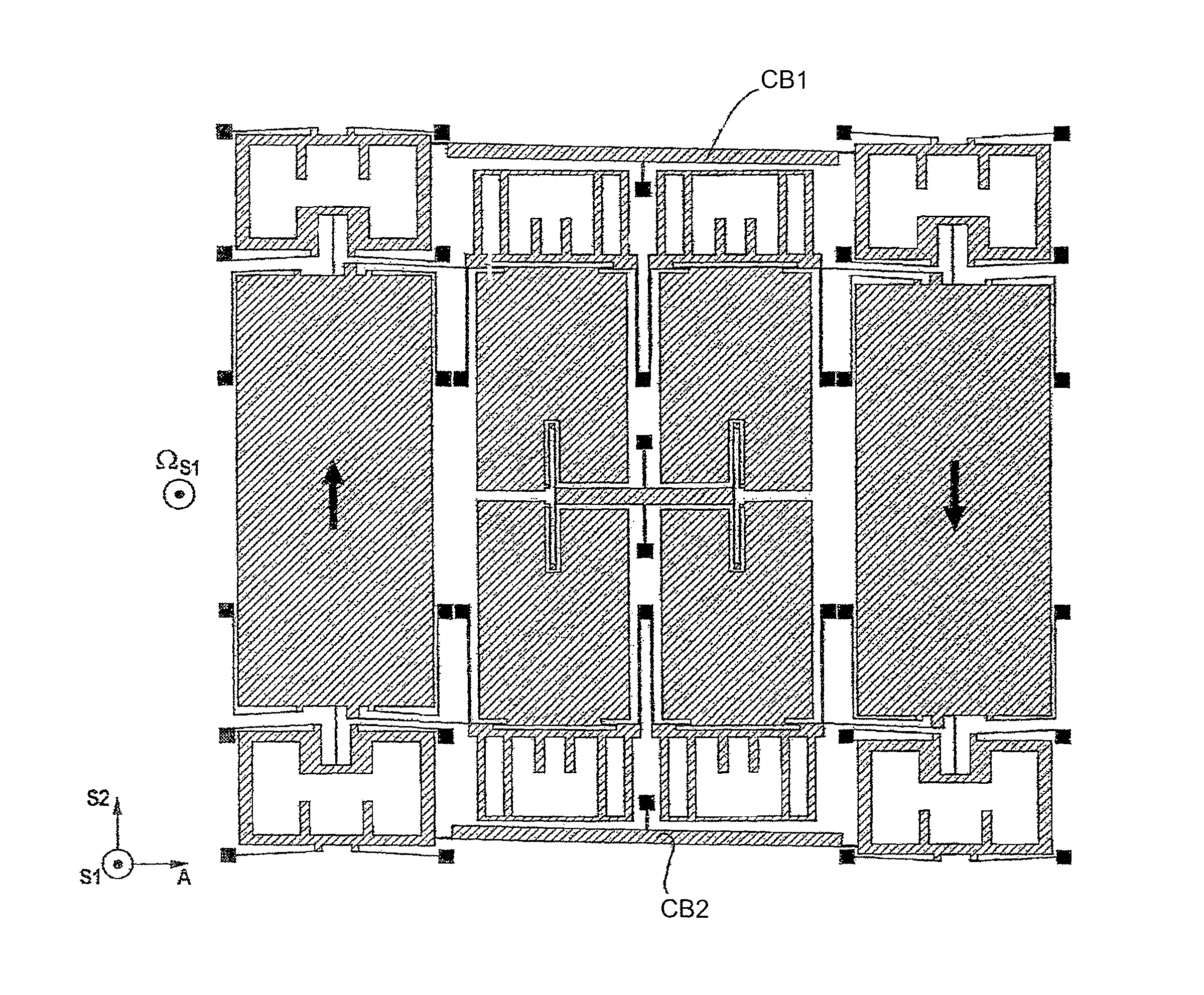
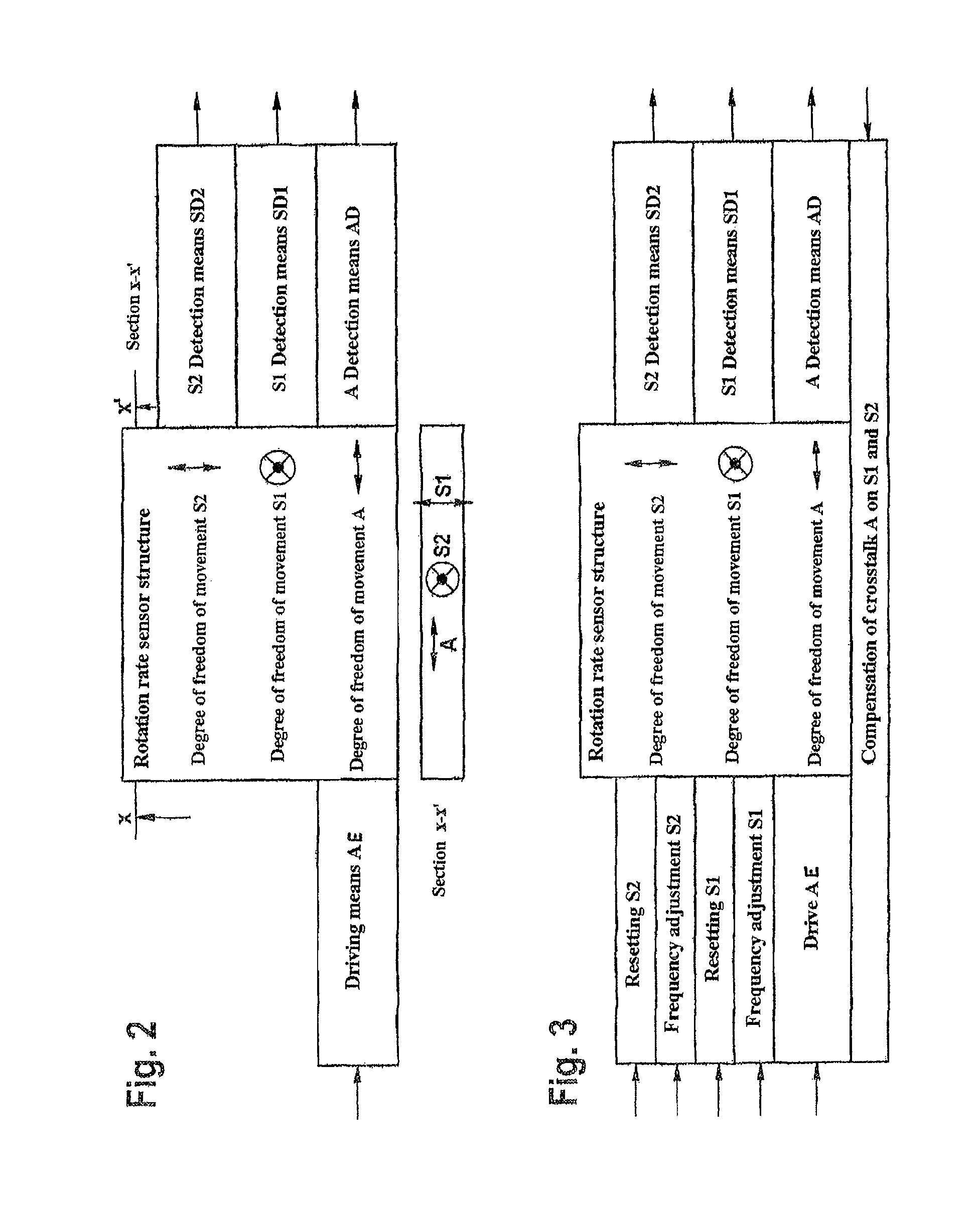
[0091]The rotation rate sensor is preferably based on the principle of a vibrating micromechanical rotation rate sensor which is composed of a system of spring elements and masses. The core is formed by a monolithic rotation rate sensor element with a degree of freedom of movement A. Here, a drive unit (AE) excites parts of the sensor structure or the entire structure (seismic mass: SM) to oscillate along this degree of freedom. The resonant frequency along the degree of freedom A or the first axis is fA. In addition, there are two further degrees of freedom of movement (S1 and S2) and / or a second and third axis in the direction of which parts of the structure or the entire structure can be deflected if the rotation rate sensor rotates about axes which are orthogonal to A, in particular in the direction of S1 and S2. The degrees of freedom of movement S1 and S2 are particularly preferably essentially orthogonal with respect to one another and orthogonal with respect to the driving d...


PUM


Abstract

A micromechanical rotation rate sensor, comprising at least one substrate, wherein the rotation rate sensor has at least a first and a second seismic mass which are coupled to one another by means of at least one coupling beam, and wherein the rotation rate sensor is embodied in such a way that it can detect rotation rates about at least a first and a second sensitive axis, wherein each seismic mass is assigned at least one actuator unit with which the deflection behavior of the seismic mass can be influenced.

Description

CROSS REFERENCE TO RELATED APPLICATIONS[0001]This application is the U.S. National Phase Application of PCT International Application No. PCT / EP2010 / 053145, filed Mar. 11, 2010, which claims priority to German Patent Application No. 10 2009 012 269.9, filed Mar. 11, 2009, the contents of such applications being incorporated by reference herein.FIELD OF THE INVENTION[0002]The invention relates to a a micromechanical rotation rate sensor, comprising at least one substrate, wherein the rotation rate sensor has at least a first and a second seismic mass which are coupled to one another by means of at least one coupling beam, and wherein the rotation rate sensor is embodied in such a way that it can detect rotation rates about at least a first and a second sensitive axis, wherein each seismic mass is assigned at least one actuator unit with which the deflection behavior of the seismic mass can be influenced.BACKGROUND OF THE INVENTION[0003]For example in driving stability control systems...

Claims


Application Information

Patent Timeline
Patent Type & Authority Patents(United States)
IPC IPC(8): G01C19/56G01C19/574
CPCG01C19/574G01P9/04G01C19/56
Inventor SCHMID, BERNHARDGUNTHNER, STEFANSIVARAMAN, RAMNATH
Owner CONTINENTAL TEVES AG & CO OHG
Learn More