
Method and device for detecting a collision of a vehicle

Inactive Publication Date: 2019-05-23
ROBERT BOSCH GMBH
View PDF12 Cites 0 Cited by
  • Summary
  • Abstract
  • Description
  • Claims
  • Application Information

AI Technical Summary

Benefits of technology

The present invention relates to a method for identifying the type of collision that occurs between two objects, using a predictive sensor system and a classical, collision-type identification function. The method involves merging the information supplied by the predictive sensor system with the identification function to achieve a highly precise and effective identification of the collision type. The method can be flexibly adapted based on environmental information, such as the degree of overlap, collision angle, width of the collision object, and impact position. The method can also include predetermining the expected collision type and ascertaining the severity of the collision using the identification function and other information. The invention can be embodied as a device that performs the steps of the method. The technical effect of the invention is improved activation of restraining devices in the collision and efficient and reliable identification of the collision type and its severity.

Problems solved by technology

However, in collisions at an angle or having marked offset, that is, with less than the full overlap, the crumple zone of the vehicle is only partially deformed.
Due to this, only low acceleration signals, which hinder or do not allow timely detection of the collision, occur in the collision phase relevant to activation, which means that in collisions at an angle or having an offset, restraining devices are often activated too late in algorithms purely based on collision severity.

Method used


Image

  • Method and device for detecting a collision of a vehicle
  • Method and device for detecting a collision of a vehicle
  • Method and device for detecting a collision of a vehicle

Examples


Embodiment Construction

[0037]In the description below of preferred exemplary embodiments of the present invention, the same or similar reference numerals are used for the elements that are depicted in the different figures and function similarly, in which case a repeated description of these elements is omitted.

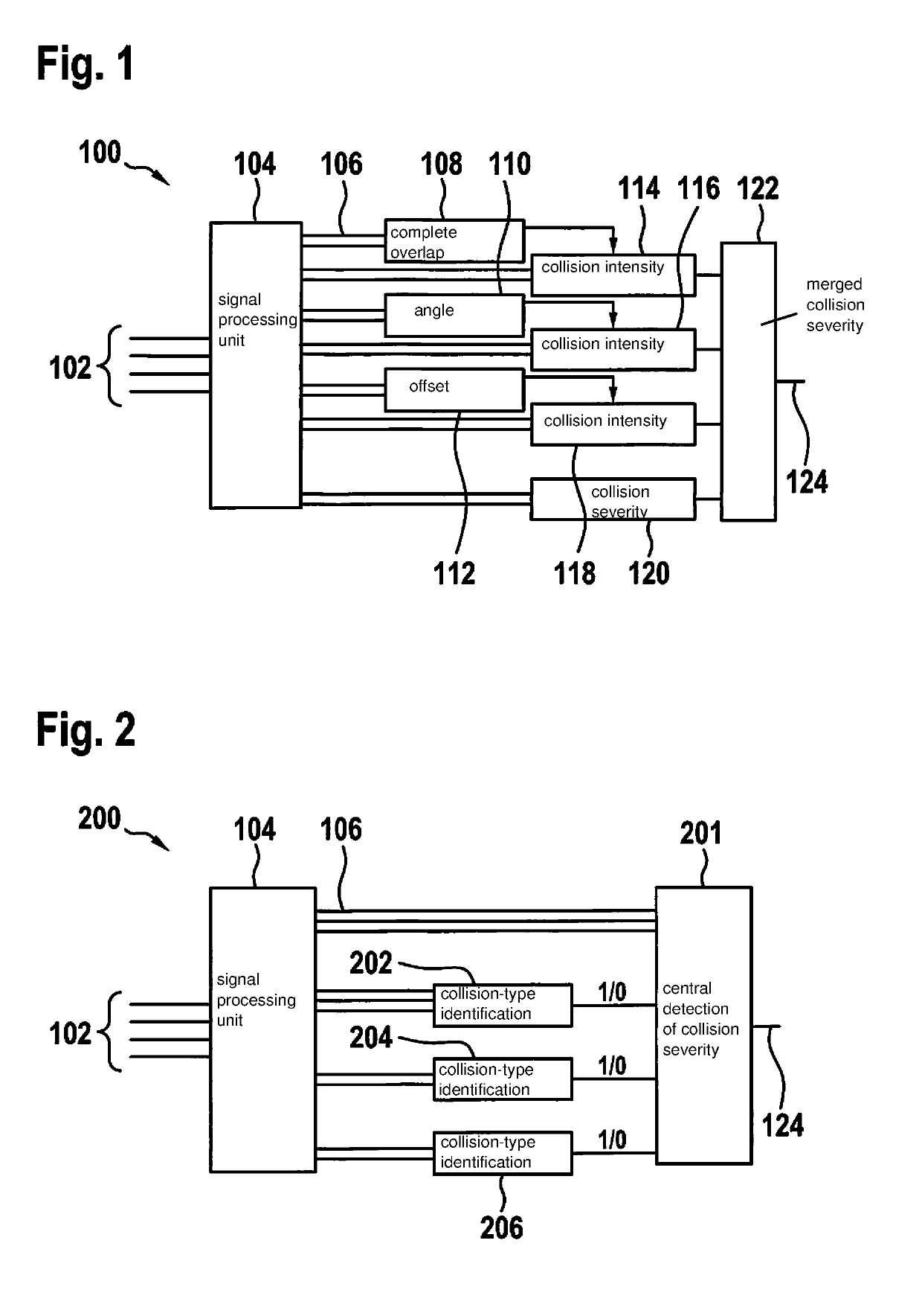
[0038]FIG. 1 shows a schematic representation of a path algorithm 100 for detecting a collision severity. As already described, existing airbag algorithms may include functions, which are for identifying the collision type, and by which the sensitivity of the evaluation of the collision severity is controlled. In principle, this may be accomplished in two ways. FIG. 1 schematically shows a so-called path algorithm. After suitable preprocessing of acceleration and pressure signals 102 by a signal processing unit 104 to form so-called signal characteristics 106, for example, by filtering or integration, then, based on a specific subset of signal characteristics, a collision-type identification is mad...


PUM


Abstract

A method for detecting a collision of a vehicle. In this context, at least one threshold value for determining at least one collision type of the collision, is modified, using an environmental information item, which represents an information item that is supplied by at least one surround sensor of the vehicle and is in regard to the collision, in order to obtain at least one modified threshold value. In a further step, the collision type is determined, using the modified threshold value and a non-environmental information item, which represents an information item that is in regard to the collision and is supplied by at least one acceleration and / or pressure sensor of the vehicle, in order to detect the collision.

Description

CROSS REFERENCE[0001]The present application claims the benefit under 35 U.S.C. § 119 of German Patent Application No. DE 102017220910.0 filed on Nov. 23, 2017, which is expressly incorporated herein by reference in its entirety.FIELD[0002]The present invention is directed to a method and a device for detecting a collision of a vehicle. The present invention also includes a computer program.BACKGROUND INFORMATION[0003]An air bag control unit seated on the vehicle tunnel is typically used to detect vehicle collisions. The algorithm used for detecting head-on collisions is based primarily on acceleration signals in the longitudinal direction (x-direction). Generally, the acceleration sensor is seated in the central airbag control unit on the vehicle tunnel, but may also be installed externally. In addition to this central x-sensor, further sensors are used, such as a central acceleration sensor measuring in the longitudinal direction (y-direction) or externally mounted acceleration se...

Claims


Application Information

Patent Timeline
IPC IPC(8): G01L5/00G07C5/08
CPCG01L5/0052G07C5/08G07C5/0841
Inventor LANG, GUNTHER
Owner ROBERT BOSCH GMBH
Learn More