Optical sectioning of a sample and detection of particles in a sample

a technology of optical sectioning and sample, applied in the field of optical sectioning sample, can solve the problems of poor quality image, difficult or impossible accurate count, and the need for rather expensive equipment for flow cytometry

Active Publication Date: 2014-07-15
KONINKLJIJKE PHILIPS NV
View PDF65 Cites 36 Cited by
  • Summary
  • Abstract
  • Description
  • Claims
  • Application Information

AI Technical Summary

Benefits of technology

[0112]The apparatus and method according to the present invention may determine the microbial activity of one or more biological organisms located in sample containers from a plurality of optical sectionings. The control unit may be adapted to sequentially acquire the optical sectionings. In one embodiment, said optical sectionings are sequentially acquired from a sample container with a second interval in time between two subsequent optical sectionings from the sample container. The interval may vary depending on the measurement to be performed. The second time interval may be below about 3600 seconds, such as below 1800 seconds, such as below 900 seconds, such as below 600 seconds, such as below 300 seconds, such as below 120 seconds, such as below 60 seconds, such as below 30 seconds, such as below 10 seconds, such as below 5 seconds such as below 2 seconds such as below 1 seconds such as below 0.5 seconds such as below 0.2 seconds such as below 0.1 seconds, such as below 0.01 seconds such as below 0.001 seconds. If the microbial activity of the sample is high, it may be advantageous to use a short interval, while a low microbial activity may call for a longer interval without losing important information. The interval may be changed during measurement depending on the determined value of the parameter, such as changed individually for the different sample containers.

Problems solved by technology

Flow cytometry requires rather expensive equipment, firstly because the flow rate must be controlled and measured with very high accuracy to get a sufficiently precise measure of the volume, secondly because the detection system must work at short acquisition times in order to get reliable data from the particles present in the detector as they pass by.
If the sample is too thick the light will be scattered and absorbed in the sample creating a poor quality image.
Some of the particles in the sample may even be in the shadow of other particles making an accurate count difficult or impossible.
The size of the image will be limited by the resolution of the image recorder and thereby the volume of the sample that may be used in the detection and counting of the particles will be limited.
But if the concentration is high, an accurate measure may be difficult or impossible to determine.
In this case a dilution of the sample could solve the measurement problem, but this knowledge may not be present until the measurement has been carried out.
If the concentration is low the statistics for the measure will be poor, as small deviations in the count of particles or small deviations in the size of the volume may have great influence on the result.
Especially when using the method proposed by Olesen et al. in WO 2008 / 010761 for determining the distribution of different white blood cells the method may fall short.
In this case it is important to have good statistics, but the sample volume is limited and if one or more of the white blood cell types have a low count, the statistical certainties may be poor.
In one embodiment where the details of the particle are of less interest, such as for counting particles, the limitation on the particle movement is such that the counting of the particles is not influenced by the movement.
In some cases the number of possible bacteria may be limited, and the number of different agents may be limited accordingly.

Method used


Image

  • Optical sectioning of a sample and detection of particles in a sample
  • Optical sectioning of a sample and detection of particles in a sample
  • Optical sectioning of a sample and detection of particles in a sample

Examples


Embodiment Construction

[0127]Further scope of applicability of the present invention will become apparent from the detailed description given hereinafter. However, it should be understood that the detailed description and specific examples, while indicating preferred embodiments of the invention, are given by way of illustration only, since various changes and modifications within the spirit and scope of the invention will become apparent to those skilled in the art from this detailed description.

[0128]The invention is defined by the features of the independent claim(s). Preferred embodiments are defined in the dependent claims. Any reference numerals in the claims are intended to be non-limiting for their scope.

[0129]Some embodiments have been shown in the foregoing, but it should be stressed that the invention is not limited to these, but may be embodied in other ways within the subject-matter defined in the following claims.

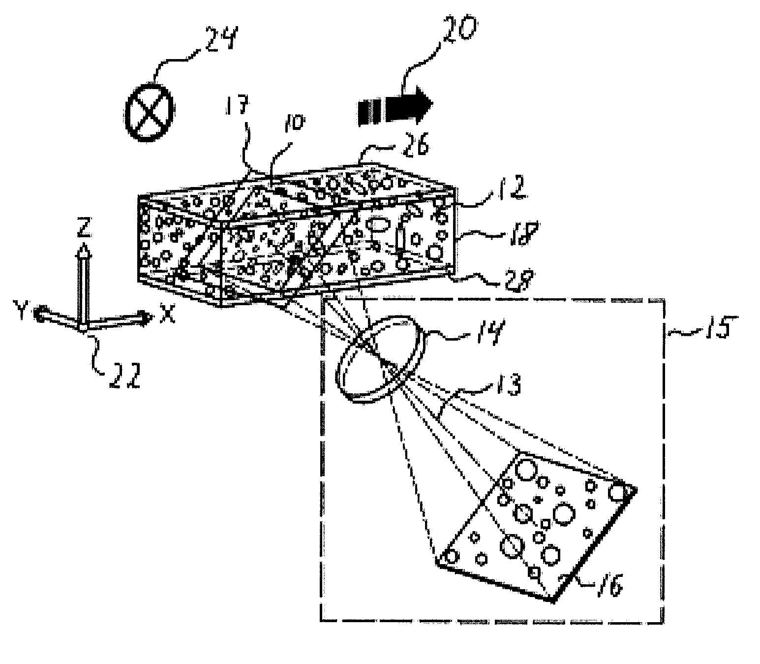
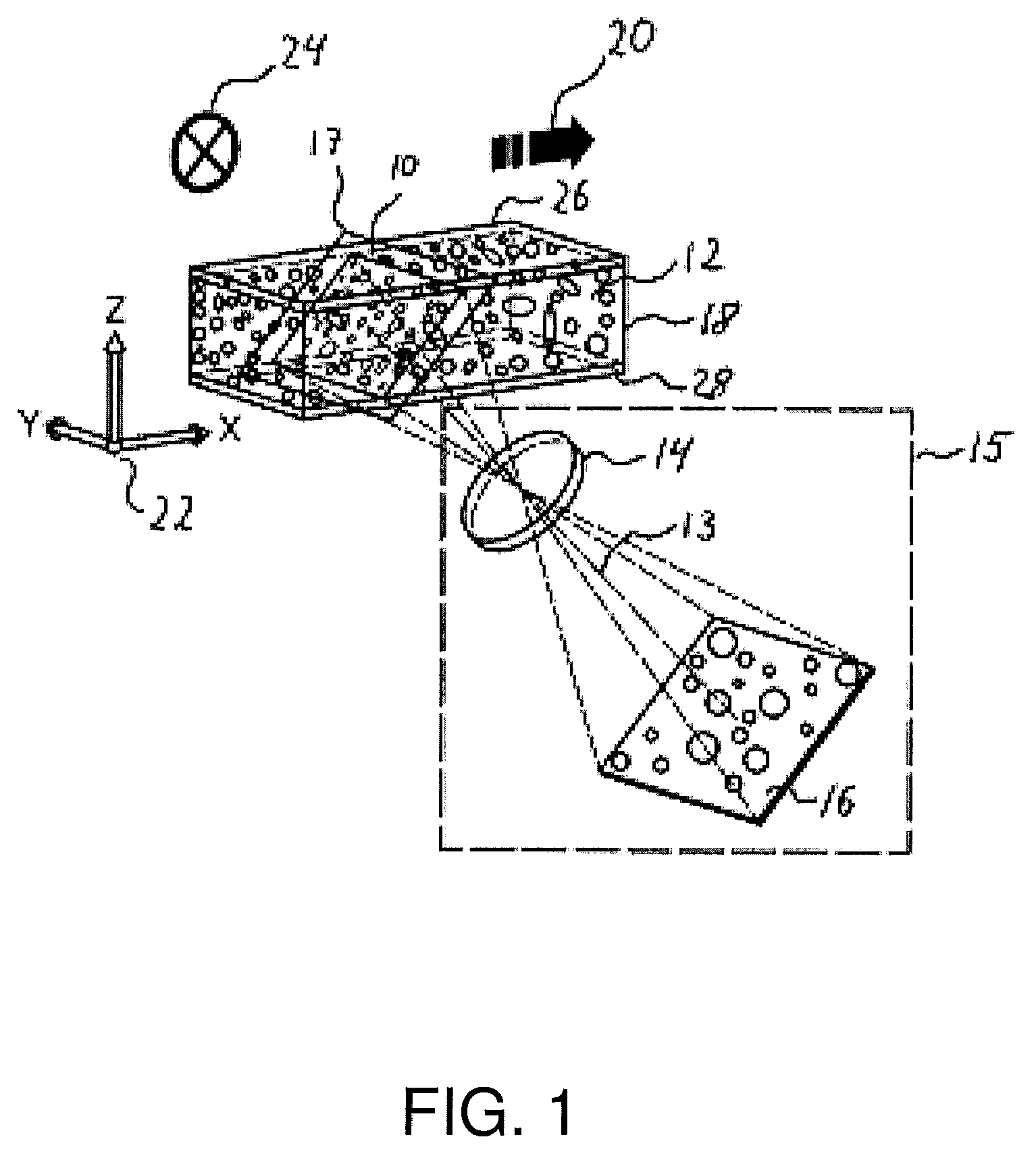
[0130]Referring to FIG. 1 one embodiment of the present invention will be descr...


PUM

PropertyMeasurementUnit
angleaaaaaaaaaa
step lengthaaaaaaaaaa
intersection angleaaaaaaaaaa

Abstract

The invention relates to an apparatus, a method and a system for obtaining a plurality of images of a sample arranged in relation to a sample device. The apparatus comprises at least a first optical detection assembly having an optical axis and at least one translation unit arranged to move the sample device and the first optical detection assembly relative to each other. The movement of the sample device and the first optical detection assembly relative to each other is along a scanning path, which defines an angle theta relative to the optical axis, wherein theta is larger than zero.

Description

FIELD OF THE INVENTION[0001]The invention relates to a method, an apparatus and a system for optical sectioning of a sample. The sample may be a confined inhomogeneous liquid sample comprising particles and the optical sectioning can be used for determining one or more parameters characterizing said particles. The invention also relates to determination of a volume of a confined sample so as to be able to determine the concentration of particles within the volume. The particles may be of biological such as embryo, bacteria, parasites, fungus, or cells. The cells may be blood cells, such as white and red blood cells, somatic cells, yeast cells, oozytes, blastocytes, cygotes, and thrombosites. The particles may also be of non-biological origin such as metal debris, water drops in oil, or air bubbles in liquids, pigments in paint, and pollution in water.BACKGROUND OF THE INVENTION[0002]The determination of the concentration of particles in a sample is often used, e.g. in connection wit...

Claims


Application Information

Patent Timeline
Patent Type & Authority Patents(United States)
IPC IPC(8): G01N17/00G01N15/14H04N13/00H04N13/02H04N13/239
CPCG01N15/1434H04N13/0055G01N15/1475G06K9/00134G06T7/0012G06T2207/10061G02B21/002G01N17/00G06T2207/30101G02B21/367G06T2207/30024G01N2015/1445G01N2015/1452H04N13/0239G01N2015/1006H04N13/0296G06T2207/10016H04N13/239H04N13/189H04N13/296G02B21/36G01N15/04G06V20/693
Inventor OLESEN, TOMVALVIK, MARTIN CHRISTIANLARSEN, NIELS AGERSNAPSANDBERG, RASMUS HELMSBY
Owner KONINKLJIJKE PHILIPS NV
Why Eureka
Try Eureka