
Ophthalmic wavefront sensor operating in parallel sampling and lock-in detection mode

a wavefront sensor and parallel sampling technology, applied in the field of wavefront sensors, can solve the problems of insufficient refractive state information, inability to provide continuous feedback, and inability to produce sufficient small microscopy illumination light sources, etc., and achieve the effect of low latency

Inactive Publication Date: 2014-07-15
CLARITY MEDICAL SYST
View PDF80 Cites 14 Cited by
  • Summary
  • Abstract
  • Description
  • Claims
  • Application Information

AI Technical Summary

Benefits of technology

The system provides continuous, accurate refractive state monitoring over a large diopter range, immune to surgical microscope illumination, allowing for real-time feedback during ophthalmic surgeries without the need for dark environments, thereby enhancing surgical efficiency and precision.

Problems solved by technology

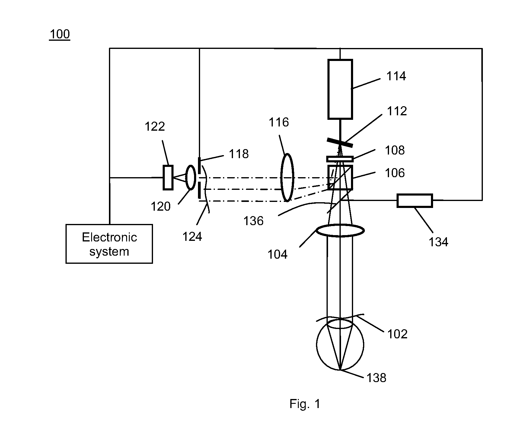
The microscope illumination light source is generally not designed to produce a sufficiently-small effective source of light at the retina that is required to generate a wavefront that reveals the patient's refractive state.
Because of this, any illumination light from the surgical microscope that is accepted by the wavefront sensor can lead to incorrect information about the patient's refractive state.
Commercially available wavefront sensors for cataract surgery, such as the ORange intraoperative wavefront aberrometer from WaveTec Vision (see for example, U.S. Pat. No. 6,736,510), do not provide continuous feedback, are limited in refractive diopter range coverage and also are not immune to interference from the illumination light of the surgical microscope.
In fact, in order to get a sufficiently precise and accurate refraction measurement using the ORange wavefront sensor, the surgeon has to pause the surgical procedure, turn off the illumination light of the surgical microscope, and has to capture multiple frames of data, which leads to additional time up to several minutes added to the cataract refractive surgery time.

Method used


Image

  • Ophthalmic wavefront sensor operating in parallel sampling and lock-in detection mode
  • Ophthalmic wavefront sensor operating in parallel sampling and lock-in detection mode
  • Ophthalmic wavefront sensor operating in parallel sampling and lock-in detection mode

Examples


Embodiment Construction

[0030]Reference will now be made in detail to various example embodiments illustrated in the accompanying drawings. While the invention will be described in conjunction with these embodiments, it will be understood that it is not intended to limit the invention to any embodiment. On the contrary, it is intended to cover alternatives, modifications, and equivalents as may be included within the spirit and scope of the invention as defined by the appended claims. In the following description, numerous specific details are set forth in order to provide a thorough understanding of the various embodiments. However, the present invention may be practiced without some or all of these specific details. In other instances, well known process operations have not been described in detail in order not to unnecessarily obscure the present invention. Further, each appearance of the phrase an “example embodiment” at various places in the specification does not necessarily refer to the same example...


PUM


Abstract

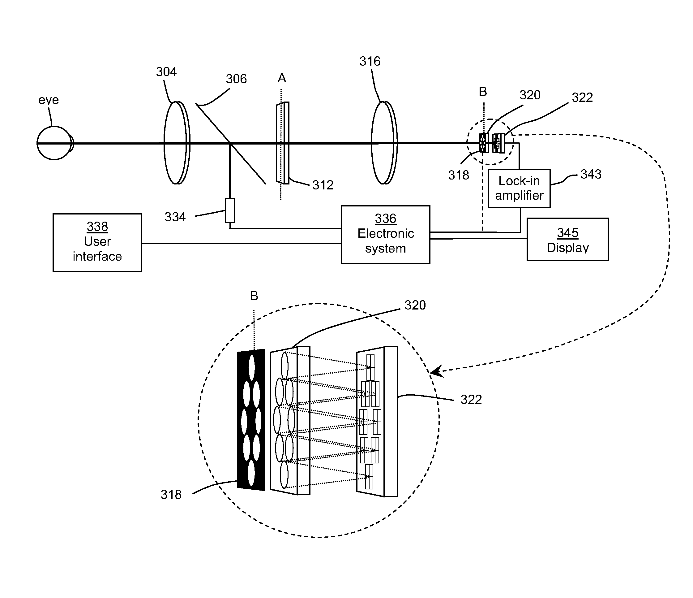
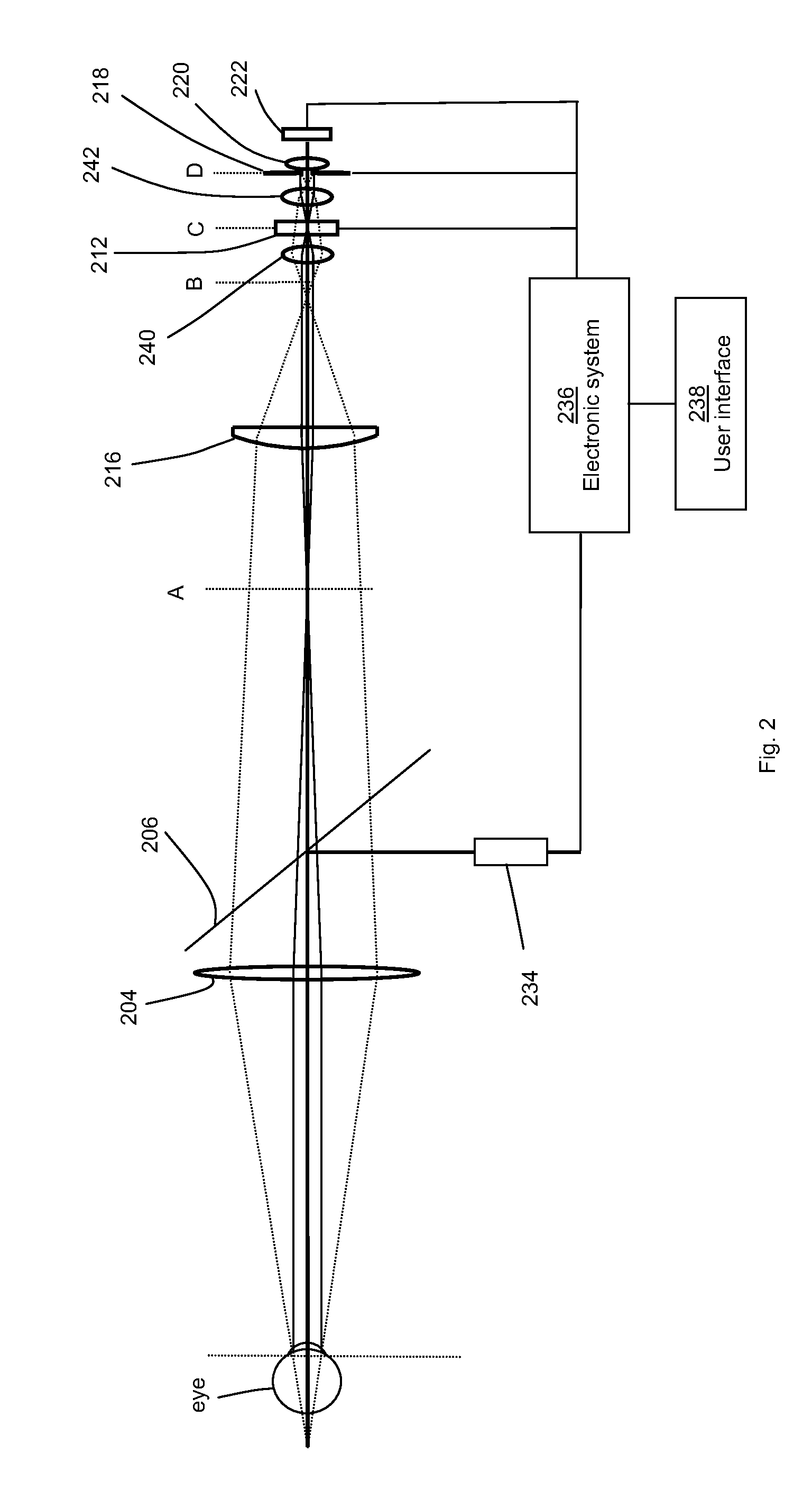
One embodiment of the present invention is an ophthalmic wavefront sensor for use with an ophthalmic microscope to provide continuous measurements of the refractive state of an eye. The wavefront sensor operates in both parallel sampling and lock-in detection mode by synchronizing the pulsing of the light source with a multiple number of position sensing devices / detectors used for detecting the centroid position of the sampled sub-wavefronts. Other embodiments include a beam scanner to sample selected portions of the wavefront and a live image sensor and a tracking deflector.

Description

RELATED APPLICATIONS[0001]This application is a continuation-in-part of application U.S. patent application Ser. No. 13 / 198,442 entitled A Large Diopter Range Real Time Wavefront Sensor, filed Aug. 4, 2011, which is a continuation-in-part of application Ser. No. 12 / 790,301 entitled Adaptive Sequential Wavefront Sensor With Programmed Control, filed May 28, 2010, which is a division of application Ser. No. 11 / 761,890 entitled Adaptive Sequential Wavefront Sensor and its Applications, filed Jun. 12, 2007, now U.S. Pat. No. 7,815,310 issued Oct. 19, 2010, which is a continuation-in-part of application Ser. No. 11 / 335,980 entitled Sequential Wavefront Sensor, filed Jan. 20, 2006, now U.S. Pat. No. 7,445,335 issued Nov. 4, 2008 and this application is also a continuation-in-part of application Ser. No. 13 / 154,293 entitled A Compact Wavefront Sensor Module and Its Attachment to or Integration with an Ophthalmic Instrument, filed Jun. 6, 2011 all of which are incorporated by reference for ...

Claims


Application Information

Patent Timeline
Patent Type & Authority Patents(United States)
IPC IPC(8): A61B3/14A61B3/10A61B3/103A61B3/12
CPCA61B3/1015A61B3/103A61B3/12G01J1/0414G01J1/0437G01J9/00
Inventor ZHOU, YANSHEA, WILLIAMBAKER, PHIL
Owner CLARITY MEDICAL SYST
Learn More