Surgical microscopes using optical coherence tomography and related methods

Active Publication Date: 2014-07-15
BIOPTIGEN
View PDF46 Cites 14 Cited by
  • Summary
  • Abstract
  • Description
  • Claims
  • Application Information

AI Technical Summary

Benefits of technology

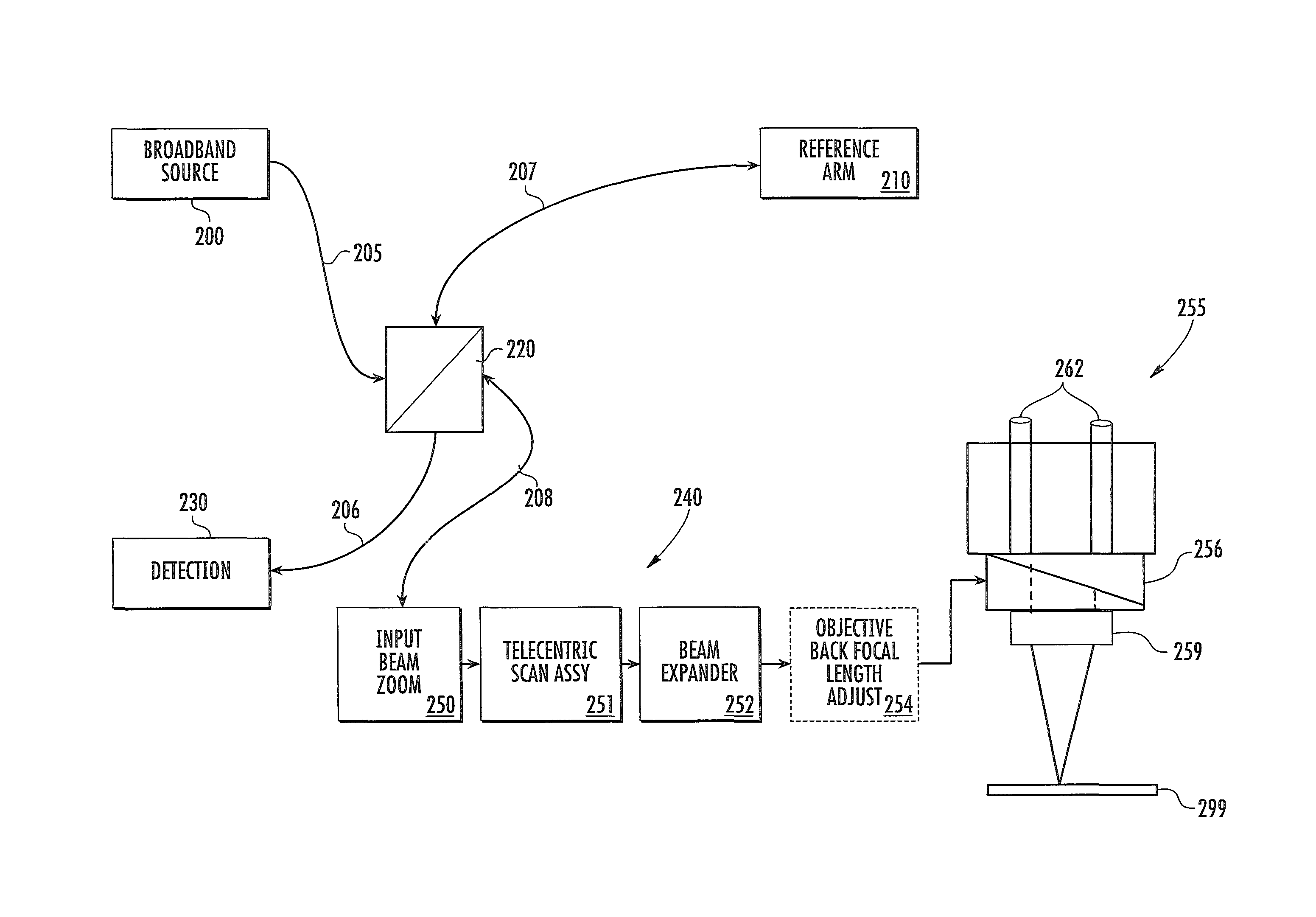
The present invention provides optical coherence tomography (OCT) systems for integration with a microscope. The OCT system includes a sample arm with an input beam zoom assembly and a scan assembly including a beamsplitter and a telecentric scanning mirror. The OCT beam is set to a specific numerical aperture and focal position for the microscope objective. The OCT system may be used in conjunction with a surgical procedure where the OCT system can visualize a first region of interest with a first numerical aperture and a first focal position and then perform a surgical procedure involving the first region of interest. The OCT system can also visualize a second region of interest with a second numerical aperture and a second focal position and then perform a surgical procedure involving the second region of interest. The OCT system can also include an aberration compensator and an aperture adjustment to accommodate for variances in the focal length of the microscope objective. The OCT system can be used in eye imaging where the eye is positioned posterior to the pupil plane of the microscope objective. The OCT system can also include a beamsplitter and a dichroic filter for imaging in a specific spectral range. The methods of the present invention include setting a first region of interest for OCT imaging, acquiring at least one OCT image, performing a surgical procedure involving the first region of interest, and acquiring at least one OCT image of a second region of interest.

Problems solved by technology

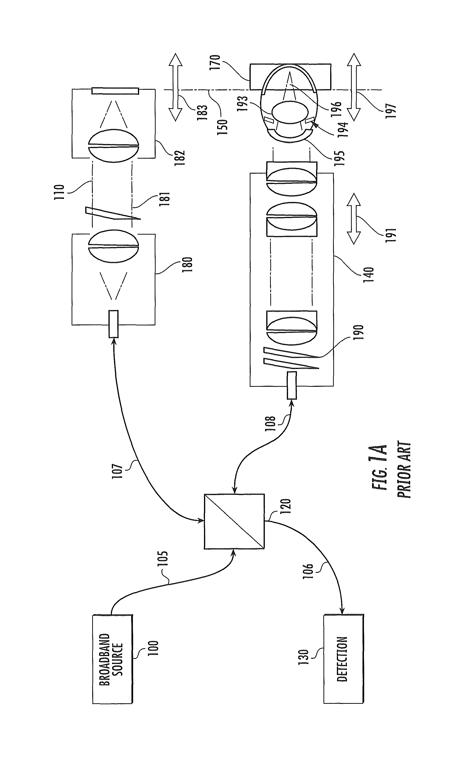
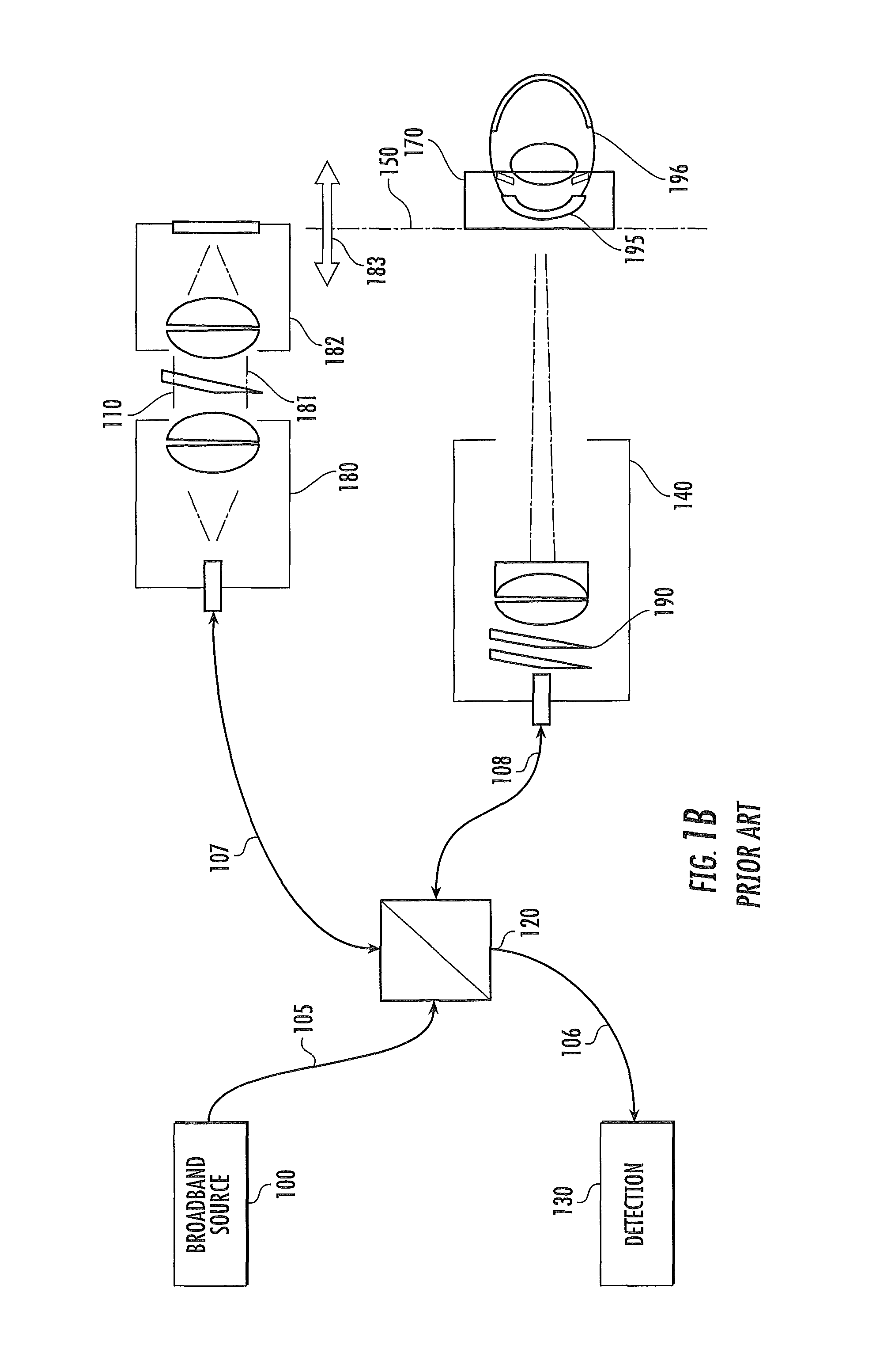
At this working distance, which provides a suitable field of access for the manual work of the surgeon, the field of view within a patient eye may be quite limited.
Thus, retinal imaging typically requires very high resolution, but not necessarily a large DOF.
The presence of the telescope lens set 167 provides beam shaping to maximize the numerical aperture of the system, potentially improving the lateral resolution of the images produced by the system, however, the system illustrated in FIG. 1E offers limited flexibility in modifying or controlling the characteristic of the scanning beam.

Method used


Image

  • Surgical microscopes using optical coherence tomography and related methods
  • Surgical microscopes using optical coherence tomography and related methods
  • Surgical microscopes using optical coherence tomography and related methods

Examples


Embodiment Construction

[0078]The present inventive concept will be described more fully hereinafter with reference to the accompanying figures, in which embodiments of the inventive concept are shown. This inventive concept may, however, be embodied in many alternate forms and should not be construed as limited to the embodiments set forth herein.

[0079]Accordingly, while the inventive concept is susceptible to various modifications and alternative forms, specific embodiments thereof are shown by way of example in the drawings and will herein be described in detail. It should be understood, however, that there is no intent to limit the inventive concept to the particular forms disclosed, but on the contrary, the inventive concept is to cover all modifications, equivalents, and alternatives falling within the spirit and scope of the inventive concept as defined by the claims. Like numbers refer to like elements throughout the description of the figures.

[0080]The terminology used herein is for the purpose of...


PUM


Abstract

Some embodiments of the present inventive concept provide optical coherence tomography (OCT) systems for integration with a microscope. The OCT system includes a sample arm coupled to the imaging path of a microscope. The sample arm includes an input beam zoom assembly including at least two movable lenses configured to provide shape control for an OCT signal beam; a scan assembly including at least one scanning mirror and configured for telecentric scanning of the OCT signal beam; and a beam expander configured to set the OCT signal beam diameter incident on the microscope objective. The shape control includes separable controls for numerical aperture and focal position of the imaged OCT beam.

Description

CLAIM OF PRIORITY[0001]The present application claims priority from U.S. Provisional Application No. 61 / 620,645, filed Apr. 5, 2012, the disclosure of which is hereby incorporated herein by reference as if set forth in its entirety.STATEMENT OF GOVERNMENT SUPPORT[0002]This inventive concept was funded in-part with government support under Grant Application ID R44EY018021-03 by the National Institutes of Health, National Eye Institute. The United States Government has certain rights in this inventive concept.FIELD[0003]The present inventive concept relates to surgical microscopes and, more particularly, to ophthalmic surgical microscopes using optical coherence tomography (OCT).BACKGROUND[0004]Surgical microscopes provide a magnified view of the operating field to the surgeon. Ophthalmic surgical microscopes are commonly stereo zoom microscopes with binocular view ports for the surgeon, and frequently have one or two observer view ports at ninety degrees (left and right) to the surge...

Claims


Application Information

Patent Timeline
IPC IPC(8): G02B21/00A61B3/13G01B9/02A61B3/10A61B3/00A61B5/00A61B3/14
CPCG02B21/0012A61B3/13A61B5/0066G02B21/0048A61B3/102G01B9/02091G01B9/02039A61B3/132G02B1/11G02B21/006G02B21/02G02B21/025G02B27/0031G02B27/0955G02B27/141
Inventor BUCKLAND, ERIC L.FARMIGA, NESTOR O.HART, ROBERT H.MURNAN, ANDREWSAXER, CHRISTOPHER
Owner BIOPTIGEN
Why Eureka
Try Eureka