
Wheel bearing device

a technology of bearing device and bearing body, which is applied in the direction of bearing unit rigid support, mechanical equipment, transportation and packaging, etc., can solve the problems of reducing the performance of bearing device and requiring a large number of man-hours to manufacture the wheel bearing devi

Inactive Publication Date: 2014-07-08
JTEKT CORP
View PDF10 Cites 1 Cited by
  • Summary
  • Abstract
  • Description
  • Claims
  • Application Information

AI Technical Summary

Benefits of technology

[0010]It is an object of the invention to provide a wheel bearing device that makes it possible to prevent occurrence of a situation where a drive shaft cannot be spline-fitted to an inner periphery of an inner shaft, without performing finishing after the assembly of the wheel bearing device, while maintaining the original performance of the wheel bearing device.

Problems solved by technology

This may lead to a decrease in the performance of the bearing device.
Therefore, a large number of man-hours are required to manufacture the wheel bearing device.

Method used


Image

  • Wheel bearing device
  • Wheel bearing device
  • Wheel bearing device

Examples


Embodiment Construction

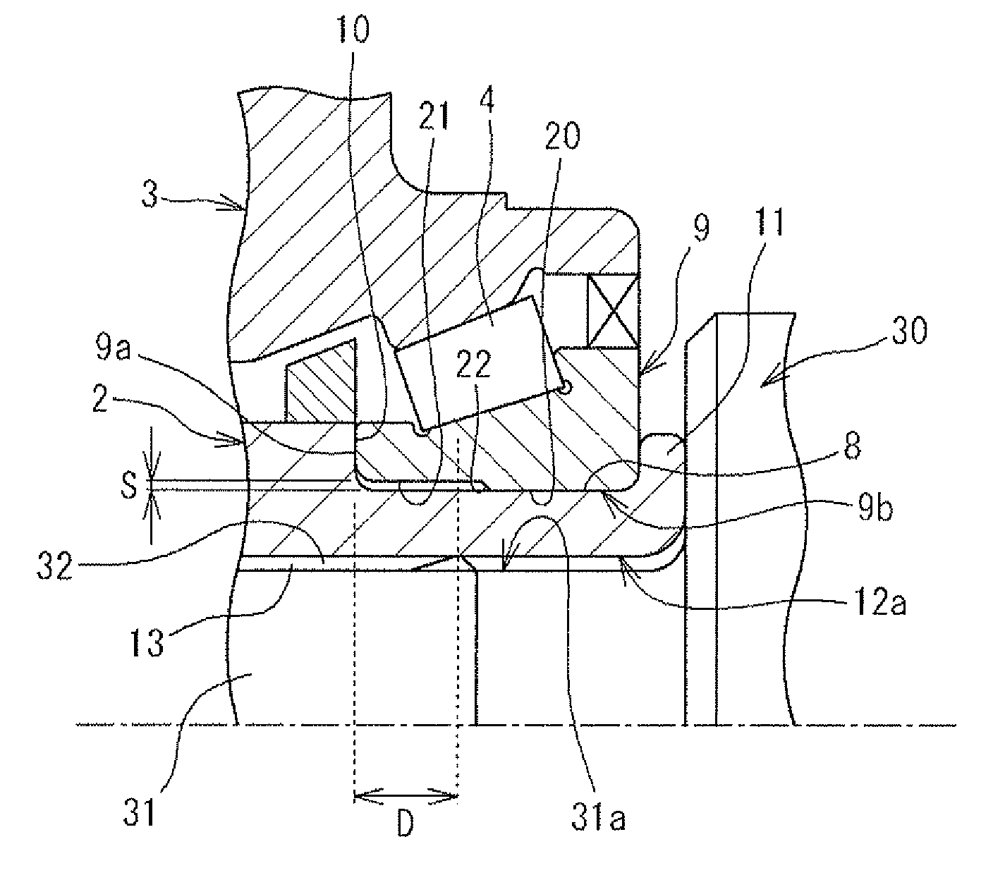
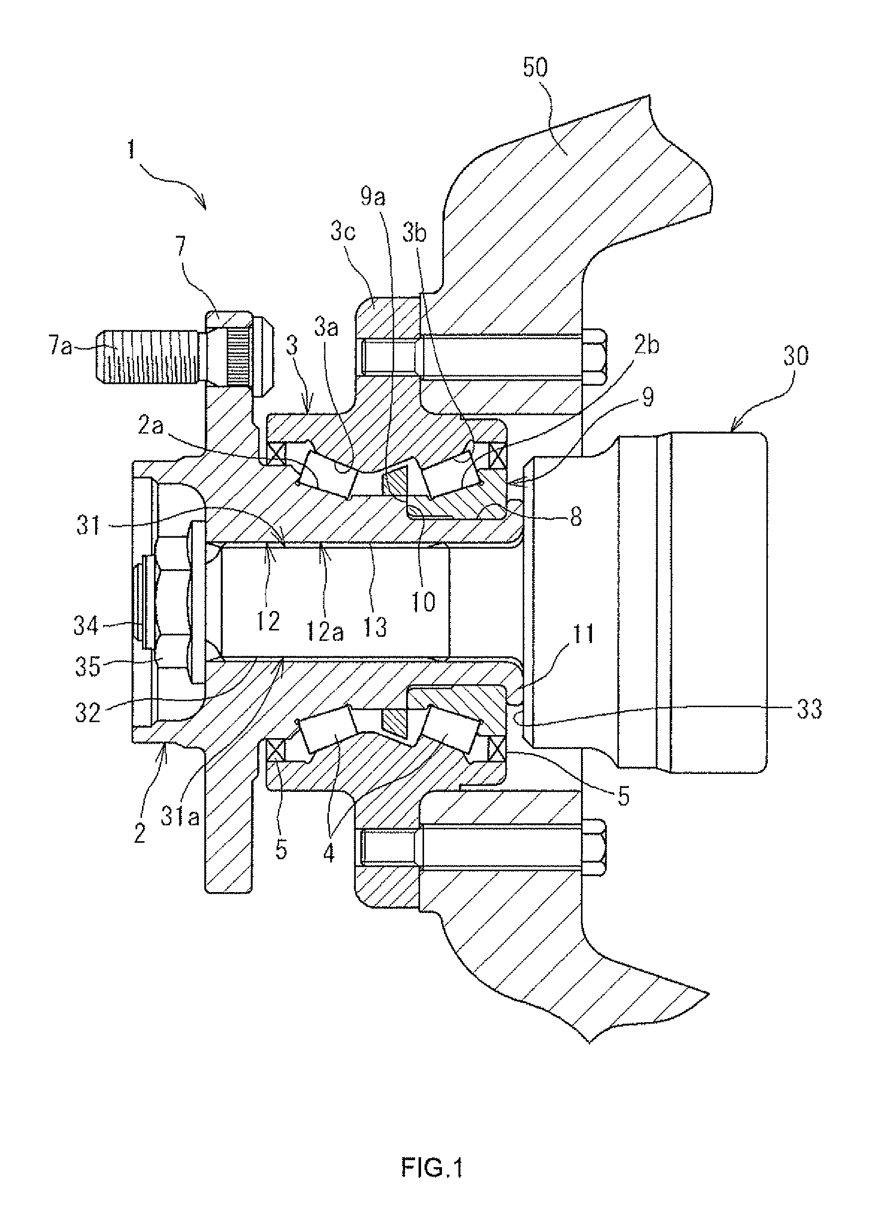
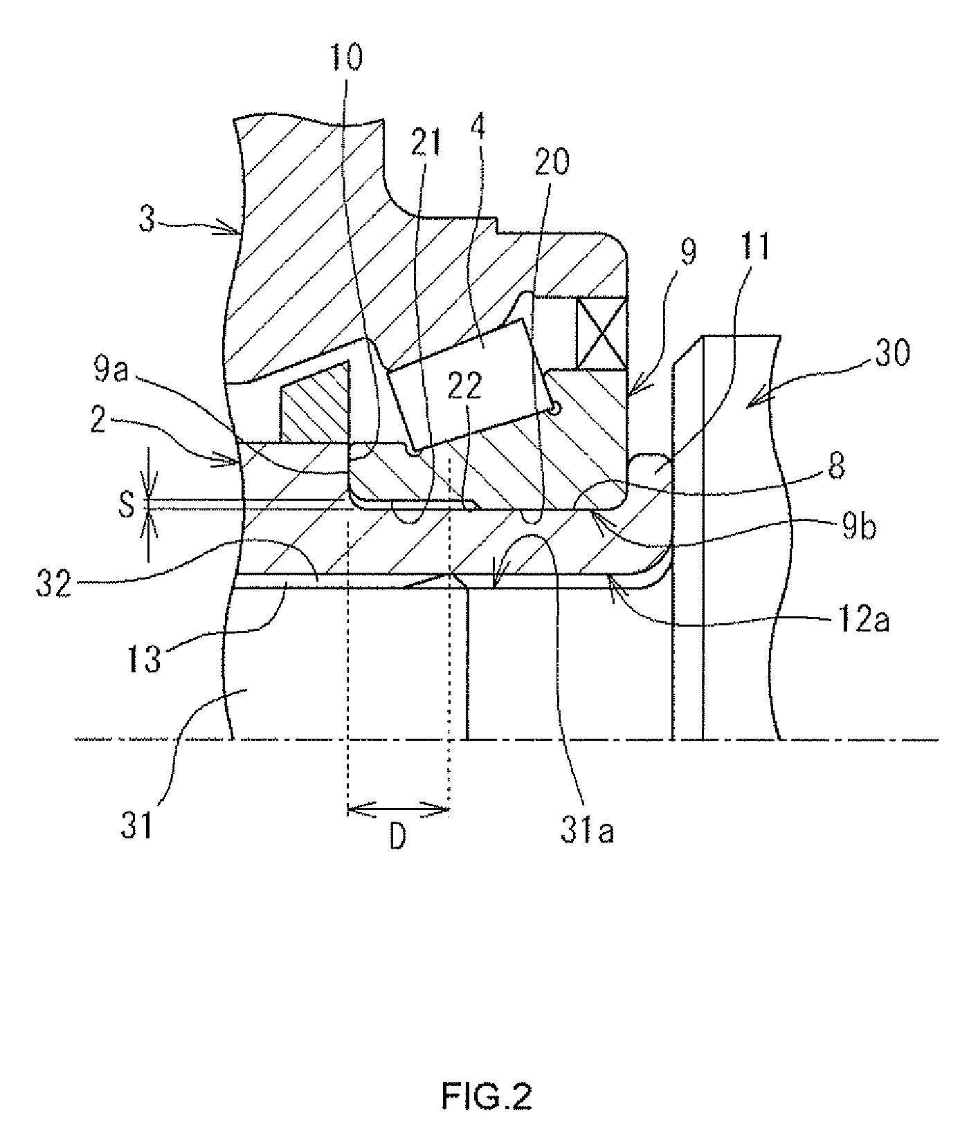
[0017]An example embodiment of the invention will be described with reference to the accompanying drawings. FIG. 1 is a sectional view of a wheel bearing device 1 according to the embodiment of the invention. The wheel bearing device 1 is used as a bearing device that supports a drive wheel of a vehicle, such as an automobile, such that the drive wheel is rotatable. The wheel bearing device 1 is fixed to a knuckle 50 on an inboard side of the wheel bearing device 1. The knuckle 50 is a member extending from the vehicle body side.

[0018]The wheel bearing device 1 constitutes a double-row tapered roller bearing. The wheel bearing device 1 includes an inner shaft 2, an outer ring 3, a plurality of tapered rollers 4 that serve as rolling elements, seal members 5, and cages (not shown). A wheel (not shown) is fitted to one end portion of the inner shaft 2 on an outboard side of the wheel bearing device 1. The outer ring 3 is arranged radially outward of the inner shaft 2 so as to be conce...


PUM


Abstract

A wheel bearing device includes an inner shaft and an inner ring member fitted onto an outer periphery of an axially-inner end portion of the inner shaft. A shaft portion coupled to the inner shaft so as to be rotatable together with the inner shaft is inserted in a center hole of the inner shaft. Spline grooves spline-fitted to spline teeth formed on an outer periphery of the shaft portion are formed in an inner periphery of the inner shaft, which defines the center hole. An annular clearance that suppresses reduction in a diameter of the inner shaft due to fitting of the inner ring member onto the inner shaft is formed between the inner ring member and the axially-inner end portion of the inner shaft, within a range where an axial range in which the spline teeth are formed overlaps with an axial range of the inner ring member.

Description

INCORPORATION BY REFERENCE[0001]The disclosure of Japanese Patent Application No. 2011-236158 filed on Oct. 27, 2011 including the specification, drawings and abstract, is incorporated herein by reference in its entirety.BACKGROUND OF THE INVENTION[0002]1. Field of the Invention[0003]The invention relates to a wheel bearing device.[0004]2. Description of Related Art[0005]Usually, a drive shaft for transmitting torque from a power source is coupled to a bearing device that supports a drive wheel of a vehicle, such as an automobile. FIG. 4 is a sectional view that shows an example of a conventional wheel bearing device for supporting a drive wheel. A wheel bearing device 100 includes a cylindrical inner shaft 101, an outer ring 103, and an inner ring member 104. A flange 101a, to which a wheel is fitted, is formed at one end portion of the inner shaft 101. The outer ring 103 is arranged radially outward of the inner shaft 101 via double-row tapered rollers 102. The inner ring member 1...

Claims


Application Information

Patent Timeline
Patent Type & Authority Patents(United States)
IPC IPC(8): F16C19/28
CPCF16C19/386B60B27/00B60B27/001B60B27/0026B60B27/0042B60B27/0084B60B27/0094B60B2900/112B60B2900/113F16C33/586F16C35/0635F16C2240/46F16C2326/02F16C43/04
Inventor TAKIMOTO, MASAO
Owner JTEKT CORP
Learn More