Aircraft cabin curtain rail assembly kit, aircraft cabin curtain rail and aircraft with an aircraft cabin having a curtain supported on such an aircraft cabin curtain rail

a technology for aircraft cabins and aircraft, which is applied in the direction of wing accessories, wing suspension devices, manufacturing tools, etc., can solve the problems of complete re-design or modification of curtain rails, and achieve the effects of easy manufacturing, improved ability, and easy manufacturing in an industrial quantity

Active Publication Date: 2014-06-24
AIRBUS OPERATIONS GMBH
View PDF13 Cites 6 Cited by
  • Summary
  • Abstract
  • Description
  • Claims
  • Application Information

AI Technical Summary

Benefits of technology

[0005]It may be beneficial to provide an aircraft cabin curtain rail that is tailored to an individually designed separation region in an aircraft cabin, wherein it may also be beneficial to provide necessary modifications very easily in order to eliminate the need for a complete re-design on late changes in the cabin configuration.
[0010]The first end of each curtain rail component is equipped with a recess that is able to receive a protrusion of a second end of another curtain rail component. Therefore, an aircraft cabin curtain rail may be easily created through creation of a chain of different curtain rail components with a pair of a fixation protrusion and a recess at each connection region. The faces of the first end and the second end connected thereto preferably flushly touch each other in a connected state, while the relative positions of the inserted fixation protrusions and the respective recesses are fixed through the fastening means.
[0013]Preferably, the fastening means is a releasable positive locking means. Hence, the fastening means is designed to be easily removed or de-activated such that the connected curtain rail components may be detached from each other again. This simplifies the process of creating an aircraft cabin curtain rail as individual curtain rail components may easily be replaced.
[0015]In another advantageous embodiment the fixation protrusion comprises a through-hole that extends perpendicularly to the local longitudinal axis of the second end, wherein a through-hole having a thread extends perpendicularly to the local longitudinal axis of the first end through an inner wall of the recess. This allows the insertion and fastening of a screw through both through-holes for fastening two curtain rail components to each other. This positive locking may easily be achieved and disengaged as well.
[0017]In another embodiment the fastening means is a locking means comprising an elongated body with a circular cross-section and at least one locking protrusion that extends perpendicularly to a longitudinal axis of the elongated body, wherein at least one lateral walling of the recess of the first end and the fixation protrusion of the second end comprise through-holes that extend perpendicularly from an outside through the first end and the second end, respectively and correspond to the cross-section of the elongated body with the at least one locking protrusion extending therefrom, wherein the position and orientation of the at least one through-hole of the first end corresponds with the position and orientation of the through-hole of the second end such that the locking body is insertable through the at least one through-hole of a first end of a first curtain rail component and a second end of a second curtain rail component in an assembled state. A combination of a first curtain rail component and a second curtain rail component with a fixation protrusion of the first curtain rail component inserted into the recess of the second curtain rail component thereby comprises two or three through-holes with the same extension direction, position and orientation. A first through-hole may extend from a lateral walling of the recess of the first end of the second curtain rail component into the recess of this first end. Directly thereafter a second trough-hole follows on, which second through-hole is located inside the fixation protrusion. On the opposite lateral wall of the recess another through-hole follows. As the elongated body of the locking means has at least one locking protrusion, for example a pin, perpendicularly extending therefrom its cross-section is not completely circular. For guiding the locking means through the lateral wallings of the recess and the fixation protrusion the through-holes require a shape that corresponds to this certain cross-section. Thereby, the locking means may only be inserted in certain discrete orientations completely through the combination of first and second curtain rail components. It may be possible that a first through-hole may have a larger shape that may equal a circular hole with a diameter exceeding the maximum local diameter of the elongated body with the at least one pin. Consequently, as the locking means may not be pulled out of the lateral walls and the fixation protrusion in other orientations a positive locking may be accomplished easily just through turning the locking means. A positive locking may thereby be accomplished either from the holder slit or from the curtain slit.
[0021]In an exemplary embodiment the cross-section of each curtain rail component is symmetrical about at least one axis. Thereby, the curtain rail may be turned at least back to front and, when the curtain rail components are symmetrical about two axes they may also be positioned upside down. This improves the ability for providing an easy to manufacture aircraft cabin curtain rail without the probability of an error during the manufacture through a wrongly oriented curtain rail component. Furthermore, these curtain rail components may easily be manufactured in an industrial quantity.

Problems solved by technology

Consequently, late changes in the design of cabin configurations may lead to the necessity of a modification or a complete re-design of a curtain rail.

Method used


Image

  • Aircraft cabin curtain rail assembly kit, aircraft cabin curtain rail and aircraft with an aircraft cabin having a curtain supported on such an aircraft cabin curtain rail
  • Aircraft cabin curtain rail assembly kit, aircraft cabin curtain rail and aircraft with an aircraft cabin having a curtain supported on such an aircraft cabin curtain rail
  • Aircraft cabin curtain rail assembly kit, aircraft cabin curtain rail and aircraft with an aircraft cabin having a curtain supported on such an aircraft cabin curtain rail

Examples


Embodiment Construction

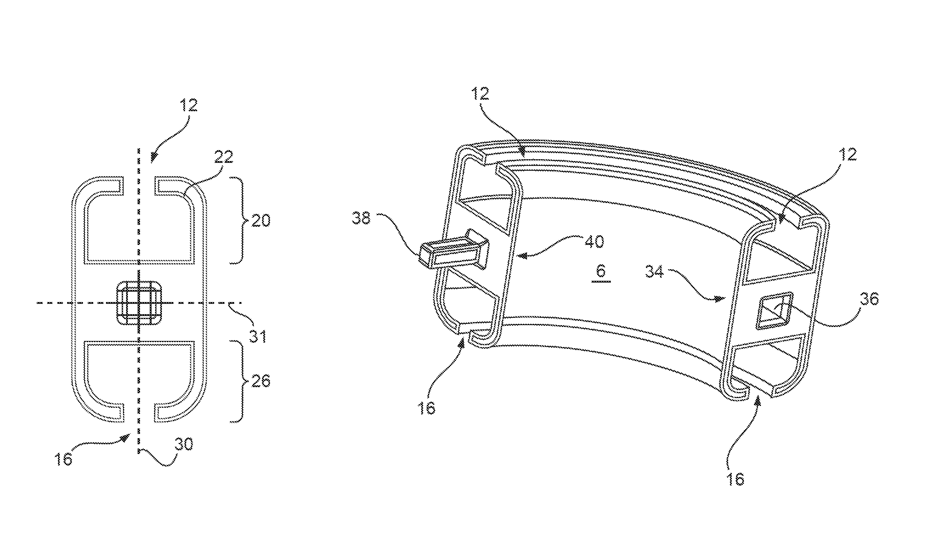
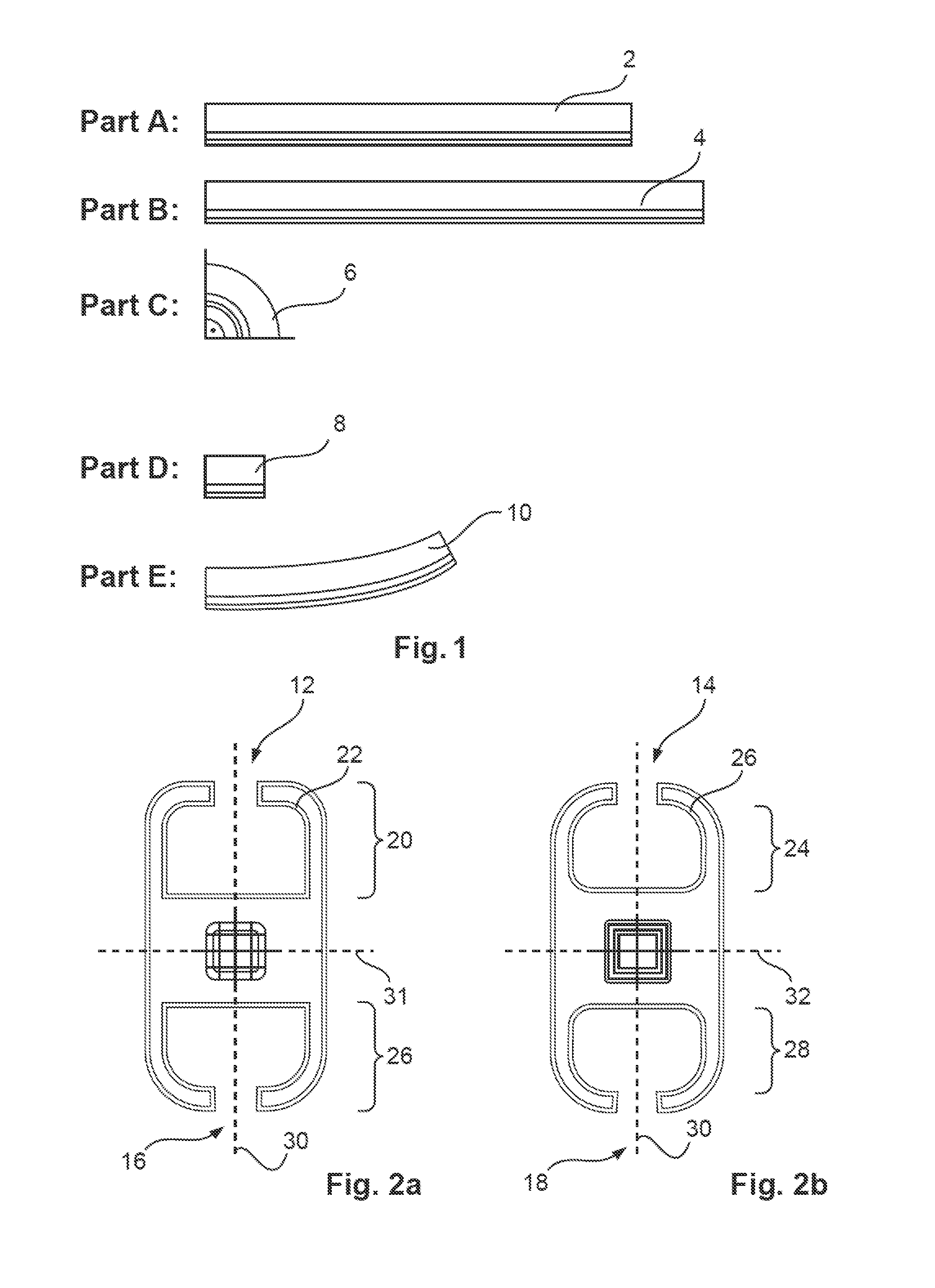
[0032]FIG. 1 shows an overview of a possible aircraft cabin curtain rail assembly kit. Exemplarily two linear or longitudinal curtain rail components 2 and 4 are named part “A” and part “B”. Part A exemplarily has a length of 50 cm; part B exemplarily has a length of 60 cm. These dimensions allow creating an aircraft cabin curtain rail with a most common lateral extension for providing a cabin zone separation for the most common commercial aircraft. The respective passageways over which the aircraft cabin curtain rail to be created spans, usually comprise a certain lateral extension for allowing a person to walk through. Often, besides lateral extension also longitudinal extensions are necessary as cabin components that define these passageways may be shifted relative to each other in a longitudinal direction. In order to provide necessary directional changes exemplarily a curved curtain rail component 6 is provided as a part “C” that has a radius of curvature of 10 cm and a curvatu...


PUM


Abstract

An aircraft cabin curtain rail assembly kit includes a plurality of curtain rail components with linear curtain rail sections and curved curtain rail sections with an angle of curvature in a range of 0-90°. Each curtain rail component has a first end and a second end. On the first end, a recess for receiving a fixation protrusion of another curtain rail component is arranged and, on the second end, a fixation protrusion for inserting into a recess of another curtain rail component is present. The recess and the fixation protrusion include a fastening means for fixating the recess and the fixation protrusion relative to each other. Each curtain rail component includes a holder slit for attaching the respective curtain rail component to an object and a curtain slit for guiding curtain rail guiding means in the curtain rail component.

Description

CROSS-REFERENCE TO RELATED APPLICATIONS[0001]This application claims the benefit of the filing date of U.S. Provisional Patent Application No. 61 / 653,568, filed May 31, 2012, the disclosure of which is hereby incorporated herein by reference.TECHNICAL FIELD[0002]The invention relates to an aircraft cabin curtain rail assembly kit, an aircraft cabin curtain rail and an aircraft with an aircraft cabin having at least two areas separated by a curtain supported on an aircraft cabin curtain rail.BACKGROUND OF THE INVENTION[0003]Usually, in common commercial aircraft curtain rails that hold separation curtains are tailored to fit into individual separation regions that provide a separation between adjacent cabin zones, for example between a passenger zone, a galley area or another passenger zone. Usually, a separation curtain may be supported on a curtain rail that extends over a spatially delimited passageway and may thereby extend in a lateral and a longitudinal direction, depending on ...

Claims


Application Information

Patent Timeline
Patent Type & Authority Patents(United States)
IPC IPC(8): A47H13/00
CPCY10T16/376Y10T16/372A47H1/06A47H1/04A47H2001/045B64D11/0023Y10T16/354
Inventor ULBRICH-GASPAREVIC, JOVANMOSLER, MICHAELWARNER, HOLGER
Owner AIRBUS OPERATIONS GMBH
Why Eureka
Try Eureka