
Torque index sensor

a technology of torque index and sensor, which is applied in the direction of underwater vessels, special data processing applications, and steering of non-deflectable wheels, etc., can solve the problems of reducing the force, affecting and affecting the speed of angular sensing, so as to improve enhance the efficiency of angular sensing

Active Publication Date: 2014-06-10
LG INNOTEK CO LTD
View PDF4 Cites 0 Cited by
  • Summary
  • Abstract
  • Description
  • Claims
  • Application Information

AI Technical Summary

Benefits of technology

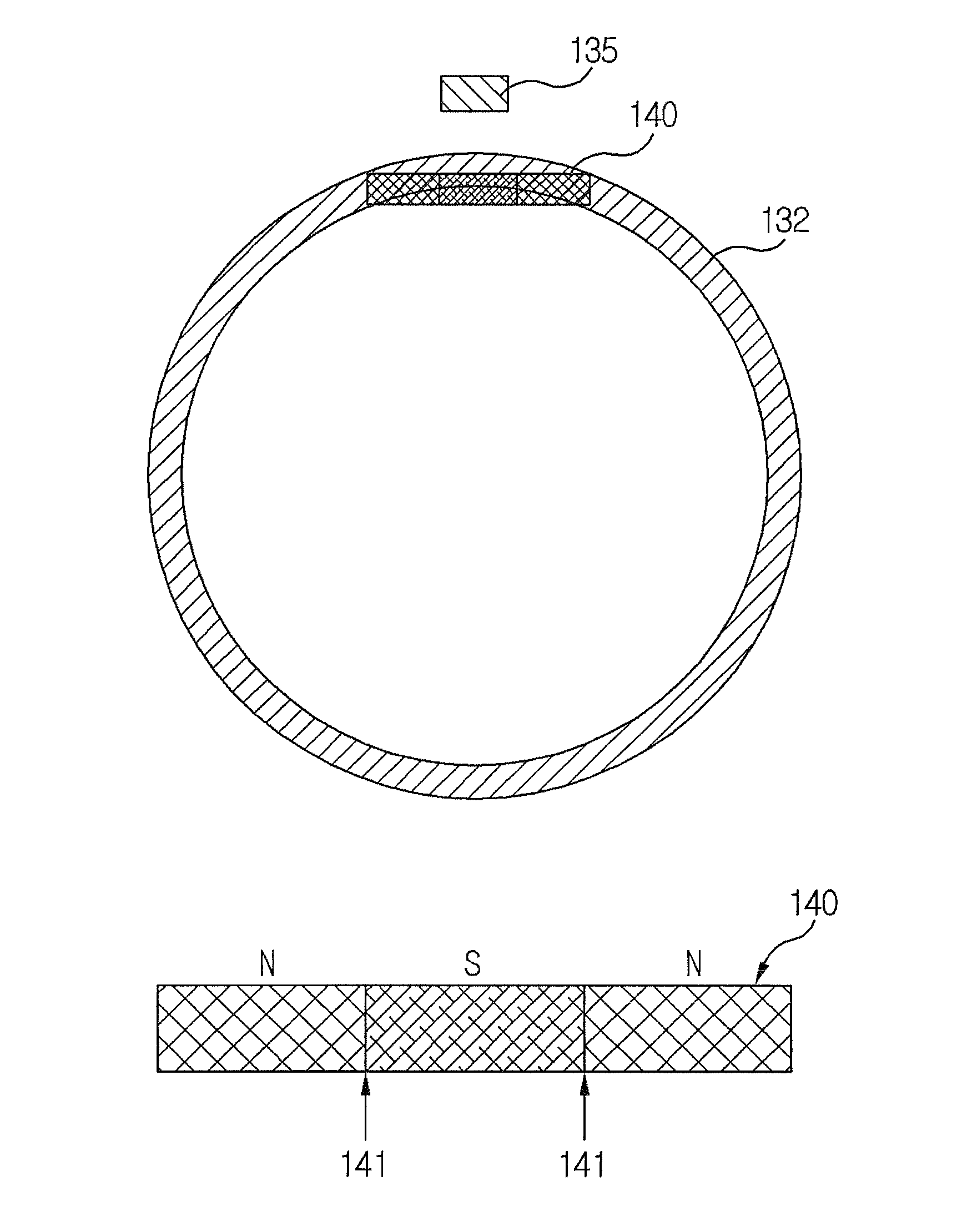
The present disclosure is directed to improve the performance of a torque index sensor used in steering systems. The invention simplifies the structure of the index magnet, which is connected to the output shaft, by shaping it as a rectangle. This shape improvement enhances the productivity and economic feasibility of the sensor. The index magnet is composed of multiple magnets that are arranged in a mutual coupling manner, which facilitates the coupling and magnetization of the magnets. The magnetic device generates an impulse signal in response to rotation of the index magnet, which further simplifies the structure and enhances the angular sensing efficiency of the sensor.

Problems solved by technology

However, an operating force may decrease to make it difficult to quickly operate the vehicle, in case there is a large resistance between wheels and road surface, or there is generated an obstacle to steering operation.
However, the device or system detecting the steering angle or the angular velocity suffers from disadvantages such as complicated fabrication processes, and a high probability of error occurrences from malfunction or erroneous operation, such that a method using an index sensor is employed.
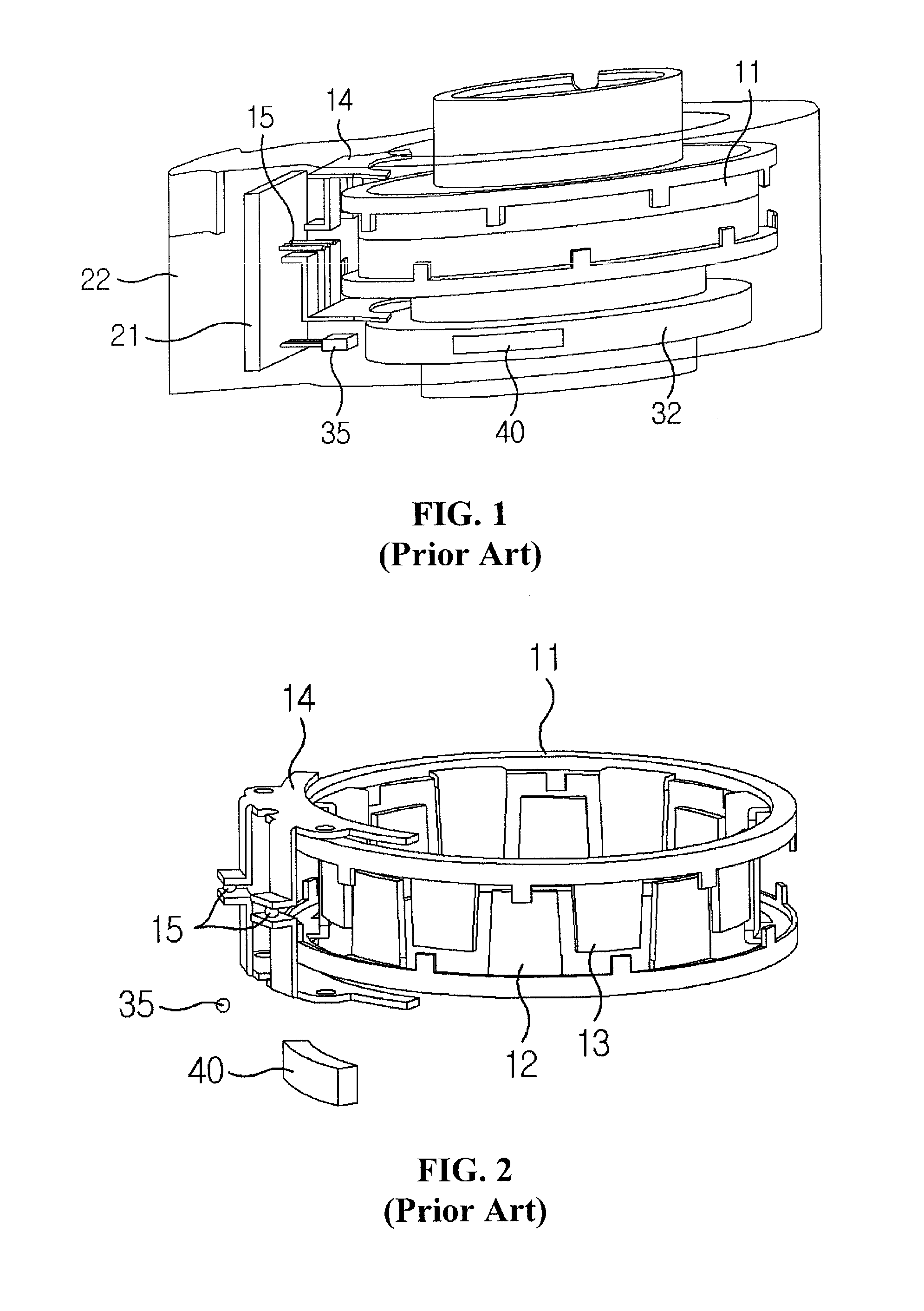
The TIS is advantageous due to structural simplicity and economic reasons, but concurrently disadvantageous due to inevitable occurrence of magnetic field interference caused by a structure in which two types of magnetization detection device are adjacently arranged.
As a result, there is generated a disadvantage of unnecessarily increasing a size of the TIS and of considering a magnetic field interference for fabricating the TIS into a compact size.
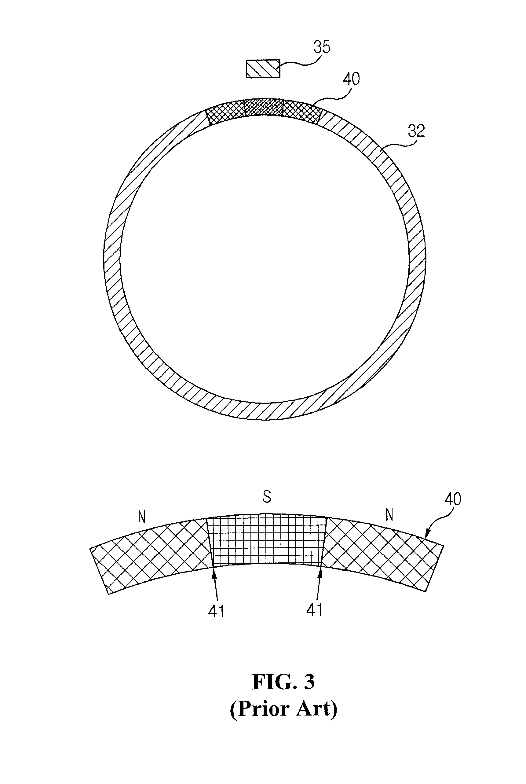
However, there exists a problem of naturally increasing a manufacturing cost and decreasing operational efficiency in the course of manufacturing and processing the index magnets (40).
The problem results in a decreased advantage of the torque index sensor for reducing the manufacturing cost and simplifying the structure.

Method used


Image

  • Torque index sensor
  • Torque index sensor
  • Torque index sensor

Examples


Embodiment Construction

[0038]Advantages and features of the present invention may be understood more readily by reference to the following detailed description of exemplary embodiments and the accompanying drawings. Detailed descriptions of well-known functions, configurations or constructions are omitted for brevity and clarity so as not to obscure the description of the present disclosure with unnecessary detail. Thus, the present disclosure is not limited to the exemplary embodiments which will be described below, but may be implemented in other forms.

[0039]In the drawings, the width, length, thickness, etc. of components may be exaggerated or reduced for the sake of convenience. Furthermore, throughout the descriptions, the same reference numerals will be assigned to the same elements in the explanations of the figures, and explanations that duplicate one another will be omitted.

[0040]Accordingly, the meaning of specific terms or words used in the specification and claims should not be limited to the ...


PUM


Abstract

A torque index sensor is configured to enhance productivity with excellent economic feasibility by simplifying a magnet structure of an index sensor unit. The torque index sensor is connected to an input shaft and an output shaft, and the torque index sensor includes a housing; an index magnet housed in the housing, connected to the output shaft to rotate with the output shaft and formed in the shape of a rectangle at a cross-sectional view; and a magnetic device secured to an interior of the housing to output a magnetization signal in response to rotation of the index magnet, such that the shape of the index magnet is simplified to a rectangle to enhance productivity and economic feasibility.

Description

CROSS-REFERENCE TO RELATED APPLICATION[0001]This application claims the benefit under 35 U.S.C. §119 of Korean Application No. 10-2010-0089367, filed Sep. 13, 2010, which is hereby incorporated by reference in its entirety.BACKGROUND OF THE DISCLOSURE[0002]1. Field of the Disclosure[0003]The present disclosure relates to a torque index sensor, and more particularly to a torque index sensor configured to enhance productivity with excellent economic feasibility by simplifying a magnet structure of an index sensor unit.[0004]2. Discussion of the Related Art[0005]In a conventional vehicle, a steering wheel connected to wheels is operated to manipulate a traveling direction. However, an operating force may decrease to make it difficult to quickly operate the vehicle, in case there is a large resistance between wheels and road surface, or there is generated an obstacle to steering operation. In order to solve the problem, a power steering system is proposed. The power steering system serv...

Claims


Application Information

Patent Timeline
Patent Type & Authority Patents(United States)
IPC IPC(8): G01B7/30G01R33/07
CPCG01L3/104G01D5/145B62D6/10G01D5/12G01L3/101G01L3/109
Inventor KANG, MINCHUL
Owner LG INNOTEK CO LTD
Learn More