
Use of the frequency spectrum of artifact in oscillometry

a technology of artifacts and oscillometry, which is applied in the field of non-invasive blood pressure monitoring, can solve the problems of inability to completely mask or otherwise render the oscillometric data useless, involuntary movements such as patient shivering, and the inability to produce high-frequency artifacts in the oscillometric data

Active Publication Date: 2014-06-03
GENERAL ELECTRIC CO
View PDF11 Cites 1 Cited by
  • Summary
  • Abstract
  • Description
  • Claims
  • Application Information

AI Technical Summary

Benefits of technology

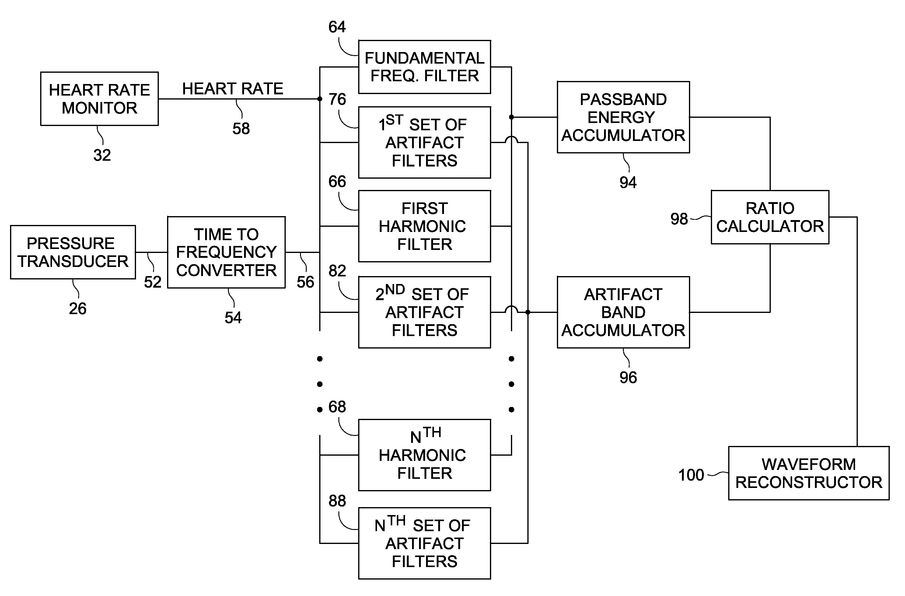
[0010]Once the oscillometric data has been converted to the frequency domain, the frequency domain oscillometric signal is filtered using one or more band pass filters having a pass band centered around the fundamental frequency and one or more harmonic frequencies. The energy within the pass bands centered around the fundamental frequency and the one or more harmonic frequencies are determined. Additionally, the method and system calculates the energy of the frequency domain oscillometric signal in at least a portion of the signal outside of the one or more pass bands. In one embodiment, the energy of the frequency domain oscillometric signal can be calculated in artifact bands positioned slightly above and slightly below the pass bands.
[0011]Once the energy within the pass bands and the energy outside of the pass bands has been calculated, the method and system calculates a ratio of the energy within the pass bands to the energy outside of the pass bands. If the calculated ratio exceeds a threshold, the system proceeds to calculate the oscillometric signal from the filtered frequency domain signal in the pass bands and computes an oscillometric envelope data point.
[0012]If the ratio does not exceed a threshold, the system can obtain additional oscillometric data at the current pressure step before moving to the next pressure step. Alternatively, the system can determine which of the pass bands to use in reconstructing the oscillometric signal. Finally, the comparison of the energy within the pass bands to the energy outside of the pass bands can be utilized by the system and method to determine a quality value of the blood pressure reading.

Problems solved by technology

However, the determination of the oscillation amplitudes is susceptible to artifact contamination.
As the oscillometric method is dependent upon detecting tiny fluctuations in measured cuff pressure, outside forces affecting this cuff pressure may produce artifacts that in some cases may completely mask or otherwise render the oscillometric data useless.
Involuntary movements such as the patient shivering may produce high frequency artifacts in the oscillometric data.
Voluntary motion artifacts, such as those caused by the patient moving his or her arm, hand, or torso, may produce low frequency artifacts.
Presently available systems may be able to determine whether or not collected oscillometric data has been corrupted with artifact; however, current filtering techniques are ineffective at removing artifacts that have similar frequency content as the desired oscillometric data.
This may greatly lengthen the time for determination of a patient's blood pressure and submit the patient to increased discomfort that is associated with the inflatable cuff restricting blood flow to the associated extremity.

Method used


Image

  • Use of the frequency spectrum of artifact in oscillometry
  • Use of the frequency spectrum of artifact in oscillometry
  • Use of the frequency spectrum of artifact in oscillometry

Examples


Embodiment Construction

[0022]FIG. 1 depicts an embodiment of a non-invasive blood pressure (NIBP) monitoring system 10. The NIBP monitoring system 10 includes a pressure cuff 12 that is a conventional flexible, inflatable and deflatable cuff worn on the arm or other extremity of a patient 14. A processing unit 16 controls an inflate valve 18 that is disposed between a source of pressurized air 20 and a pressure conduit 22. As the inflate valve 18 is controlled to increase the pressure in the cuff 12, the cuff 12 constricts around the arm of the patient 14. Upon reaching a sufficient amount of pressure within the cuff 12, the cuff 12 fully occludes the brachial artery of the patient 14.

[0023]After the cuff 12 has been fully inflated, the processing unit 16 further controls a deflate valve 24 to begin incrementally releasing pressure from the cuff 12 back through pressure conduit 22 and out to the ambient air. During the inflation and incremental deflation of the cuff 12, a pressure transducer 26, pneumatic...


PUM


Abstract

A system and method for processing oscillometric data from a plurality of pressure steps to determine the blood pressure of a patient. A heart rate monitor connected to the patient acquires the patient's heart rate. A time-to-frequency domain converter receives oscillometric data and converts the oscillometric data into the frequency domain. Based upon the calculated heart rate, the system and method filters the frequency domain oscillometric signal with pass bands centered at the fundamental frequency and at least one fundamental frequency. The energy of the frequency domain signal within the pass bands is compared to at least a portion of the energy of the frequency domain oscillometric signal outside of the pass bands. Based upon the comparison, the signal determines whether the signal at the current pressure step should be utilized in calculating the blood pressure of the patient.

Description

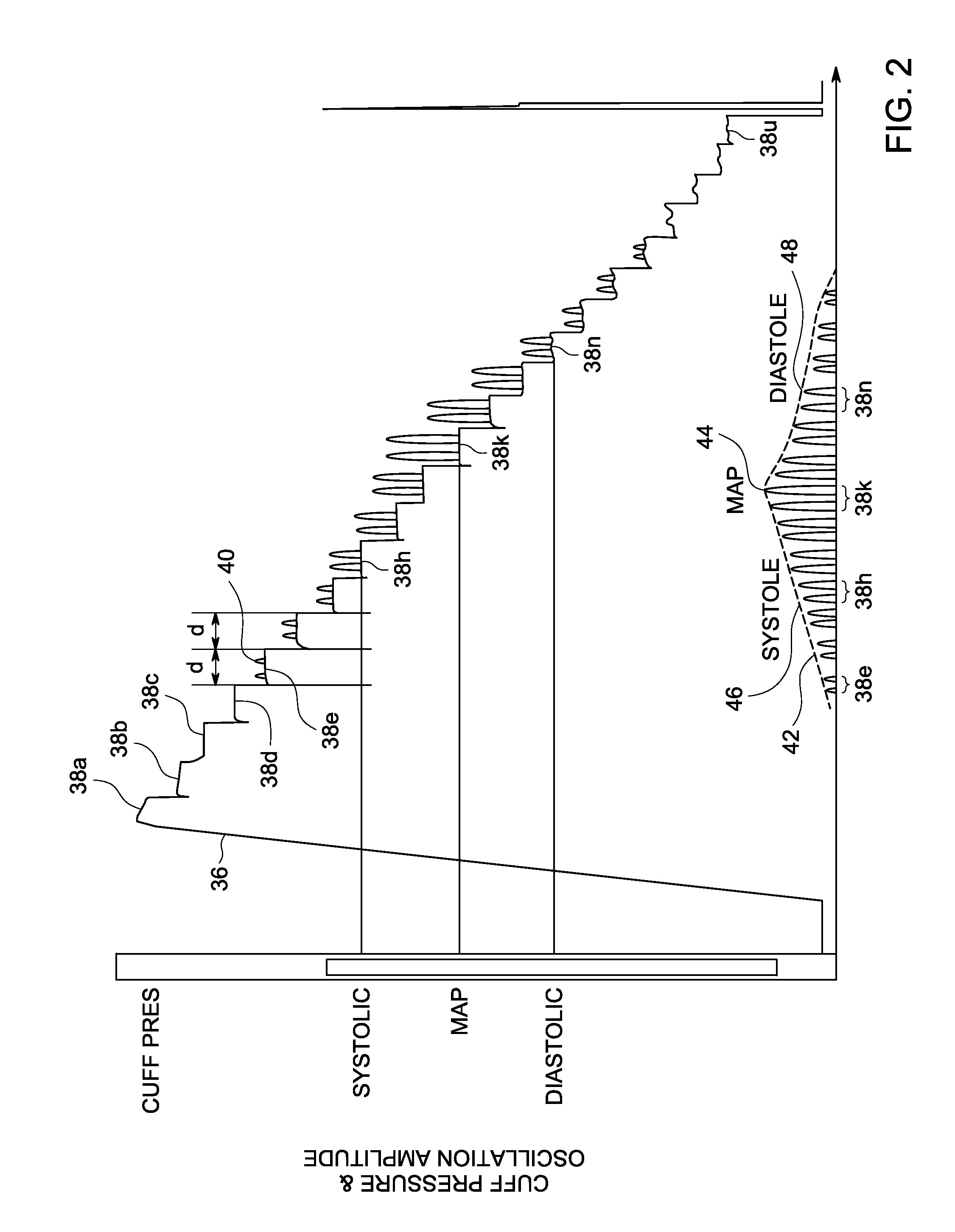
BACKGROUND OF THE INVENTION[0001]The present disclosure generally relates to the field of non-invasive blood pressure monitoring. More specifically, the present disclosure relates to a method and system for filtering signals from a patient for the improved processing of artifact contaminated oscillometric data.[0002]The human heart periodically contracts to force blood through the arteries. As a result of this pumping action, pressure pulses or oscillations exist in these arteries and cause them to cyclically change volume. The minimum pressure during each cycle is known as the diastolic pressure and the maximum pressure during each cycle is known as the systolic pressure. A further pressure value, known as the “mean arterial pressure” (MAP) represents a time-weighted average of the measured blood pressure over each cycle.[0003]While many techniques are available for the determination of the diastolic, systolic, and mean arterial pressures of a patient, one such method typically use...

Claims


Application Information

Patent Timeline
Patent Type & Authority Patents(United States)
IPC IPC(8): A61B5/02
CPCA61B5/0225A61B5/024A61B5/7257
Inventor HERSH, LAWRENCE T.KOLLURI, SAI
Owner GENERAL ELECTRIC CO
Learn More