
Lightning surge detector, surge protective device, and management system for surge protective device

a technology of surge protection device and detector, which is applied in the direction of overvoltage protection resistor, emergency protection arrangement for limiting excess voltage/current, instruments, etc., can solve the problems of not being able to monitor the operation and state of deterioration of the surge protection device in all the phases, and the characteristics of the lightning protection device will be affected, etc., to achieve the effect of simple structure, high accuracy and easy downsizing

Inactive Publication Date: 2014-05-20
SANKOSHA CORP
View PDF12 Cites 10 Cited by
  • Summary
  • Abstract
  • Description
  • Claims
  • Application Information

AI Technical Summary

Benefits of technology

Enables accurate detection of small impulsive lightning surge currents, allows for downsizing of the surge protective device, and provides visual and detailed information on the detector's operations, reducing unnecessary replacements and improving management of surge protective devices.

Problems solved by technology

The lightning protection device will undergo degradation of characteristics when the number of operations increase as a result of lightning surge currents.
This may result in burnout due to heat generation.
However, the conventional surge protective devices described in Japanese Patent Laid-Open No. 2005-150657 and Japanese Patent Laid-Open No. 2006-059888 have problems as described in (1) to (3) below.
It is not possible to grasp the number of times lightning surge currents enter.
Furthermore, it is not possible to monitor the operations and states of deterioration of plural surge protective devices all together.
Since the large number of display components are housed in the surge protective device, it is difficult to downsize the surge protective device.
An attempt to downsize the surge protective device reduces a display area of the display unit, making it difficult to see the display area visually from outside.
Furthermore, it is not possible to monitor the operations and states of deterioration of plural surge protective devices all together.
(3) Since the display unit which displays the state of deterioration of the lightning protection device is contained in the surge protective device, even if the display unit is not faulty, if the lightning protection circuit in the surge protective device deteriorates, the surge protective device needs to be discarded and replaced with a new one, resulting in waste.
Also, it is not possible to add a discrete display unit to an existing or already-installed surge protective device not preinstalled with a display unit.
This is disadvantageous and inconvenient.

Method used


Image

  • Lightning surge detector, surge protective device, and management system for surge protective device
  • Lightning surge detector, surge protective device, and management system for surge protective device
  • Lightning surge detector, surge protective device, and management system for surge protective device

Examples


first embodiment

Advantages of First Embodiment

[0127]The lightning surge detector 1 and surge protective device 50 according to this first embodiment provide advantages (a) to (e) below.

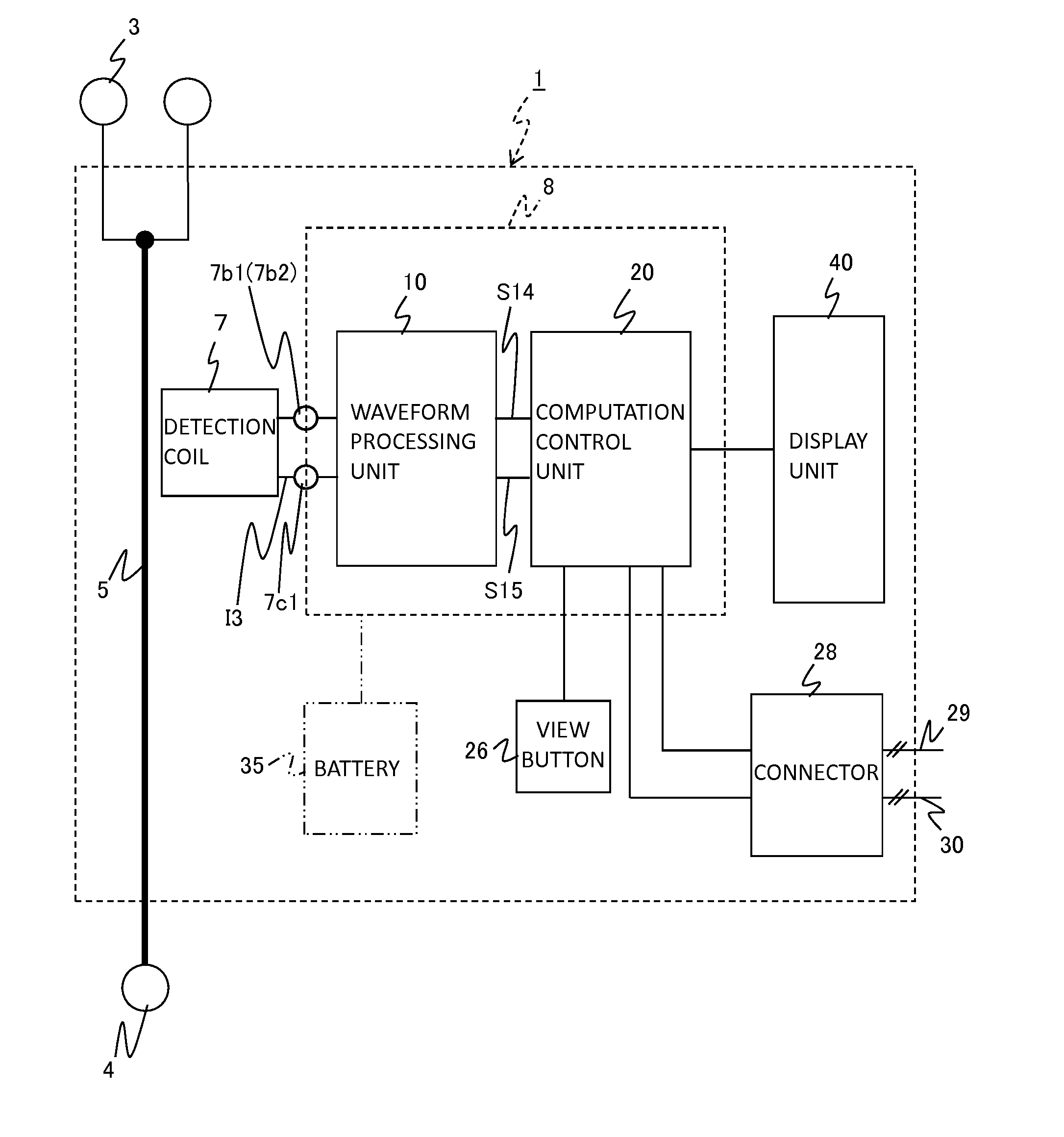
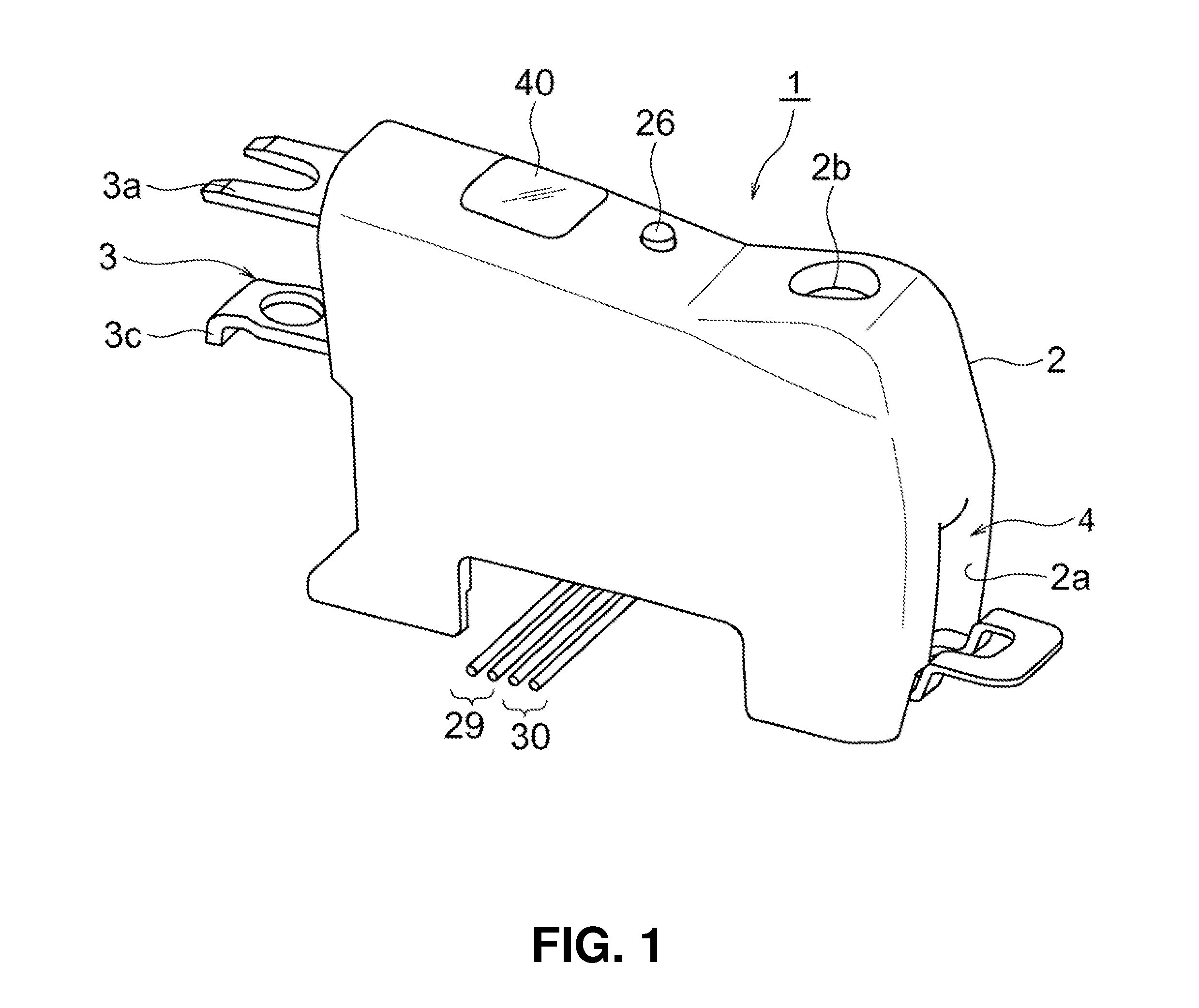
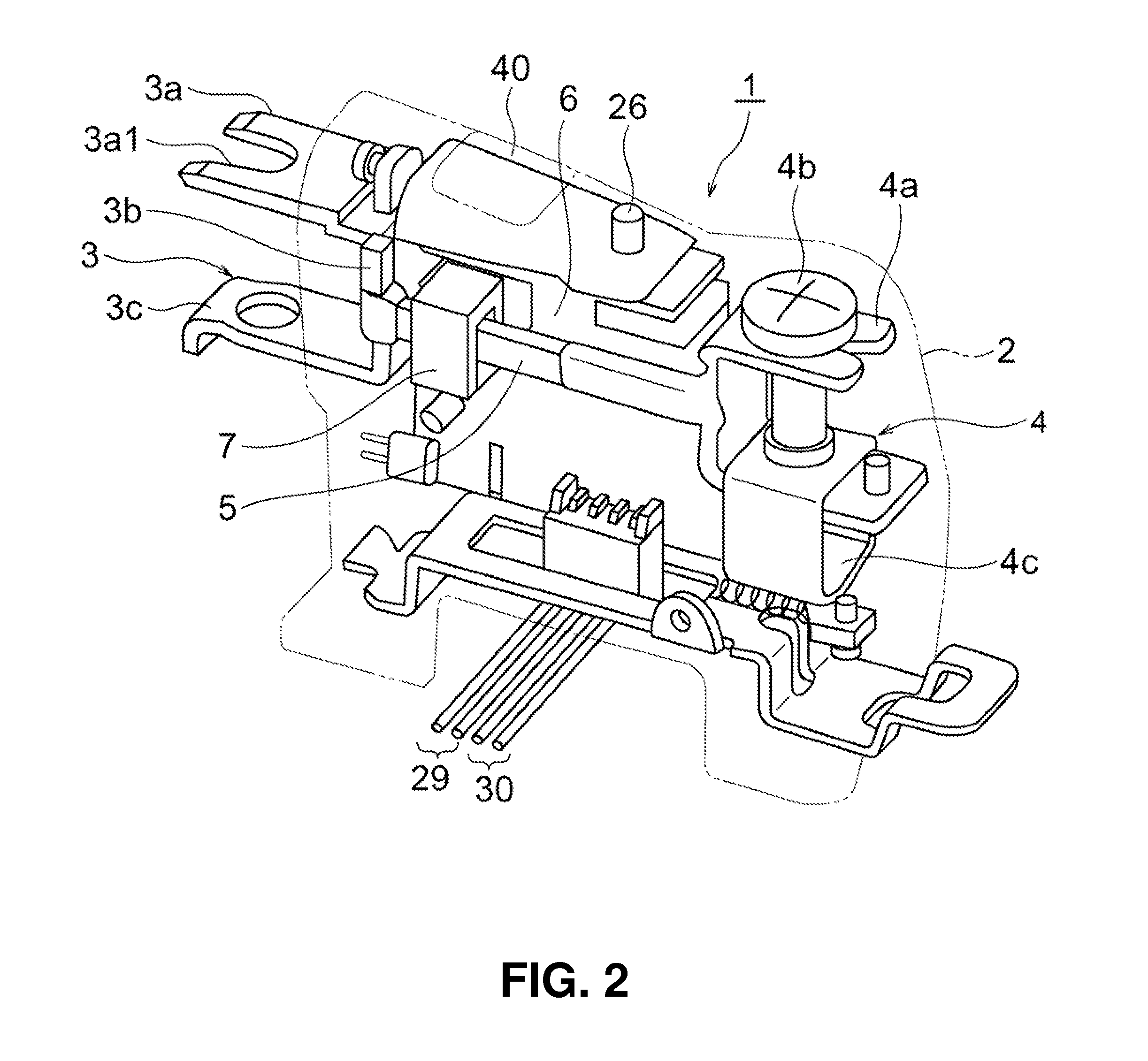
[0128](a) In the lightning surge detector 1, since the detection coil 7 with a substantially U-shaped cross section is structured to straddle the conducting coupling bar 5 via an insulating member to detect lightning surge currents with respect to ground, the portion for detecting the lightning surge currents can be downsized. In particular, the detection coil 7, which has a connection configuration such as shown in FIG. 3B or 3F can detect lightning surge currents with high accuracy without being affected by external magnetic fields. Moreover, the lightning surge detector 1, which is made up of a small number of parts, has a simple structure and readily allows its overall shape to be downsized.

[0129](b) Since the lightning surge detector 1 detects a lightning surge current flowing through the conducting coupling bar...

second embodiment

Advantages of Second Embodiment

[0147]The second embodiment provides advantages (1) to (3) below.

[0148](1) Since the management system for surge protective devices is configured such that the plurality of surge protective devices 50-1, 50-2, and 50-3 each equipped with a lightning surge detector are installed side by side closely next to the single monitor unit 90 without spacing, the management system for surge protective devices can be made small in size. Also, the CT 95 installed in the monitor unit 90 allows detailed information about the lightning surge currents flowing through the common ground wire 85 to be grasped.

[0149](2) To downsize the management system, the plurality of lightning surge detectors 1-1 to 1-3 are installed side by side closely without spacing, with the detection coil 7 in each lightning surge detector 1 having a connection configuration such as shown in FIG. 3B or 3F. Consequently, as shown in FIG. 3C or 3G, for example, when a lightning surge current flows...

third embodiment

Advantages of Third Embodiment

[0155]This third embodiment allows detailed information (e.g., the number of lightning surges, magnitudes of lightning surge currents, times of occurrence of lightning surges, replacement indicators, and the like) on the individual management blocks 100-1, 100-2, and so forth to be viewed and managed from the remote monitoring apparatus 120.

Variations of Embodiments

[0156]The present invention is not limited to the first to third embodiments described above, and various applications and variations are possible. Such applications and variations include, for example, (A) to (D) below.

[0157](A) The lightning surge detector 1 of FIGS. 1 and 2 may be changed in configuration such that the first terminal unit 3 will have a terminal style similar to that of the second terminal unit 4 or that a general-purpose lightning surge detector with a general-purpose terminal style such as a crimp terminal will be connected to various already-installed or existing surge p...


PUM


Abstract

A lightning surge detector 1 includes a first terminal unit 3 connected to a ground-side terminal unit of a surge protective device, a second terminal unit 4 connected with a ground wire, a conducting coupling bar 5 adapted to couple the first terminal unit 1 and the second terminal unit 4, a detection coil 7 placed in a vicinity of the conducting coupling bar 5 and adapted to detect a lightning surge current flowing through the conducting coupling bar 5, a waveform processing unit adapted to stretch a voltage waveform of the detected lightning surge current and thereby output a waveform-modified voltage, a computation control unit adapted to produce a calculation result of the lightning surge current from the waveform-modified voltage, and a display unit 40 adapted to display the calculation result, wherein all the above components are unitized by being housed in a casing 2.

Description

BACKGROUND OF THE INVENTION[0001]1. Field of the Invention[0002]The present invention relates to a lightning surge detector adapted to detect a lightning surge current flowing from wire lines of a power line or communications line to a ground wire and display resulting lightning surge information, a surge protective device connected with the lightning surge detector and adapted to protect power supply equipment and other protected equipment from the lightning surge current, and a management system for the surge protective device, the management system being adapted to manage the surge protective device equipped with the lightning surge detector.[0003]2. Description of the Related Art[0004]As described, for example, in Japanese Patent Laid-Open No. 2005-150657 and Japanese Patent Laid-Open No. 2006-059888, surge protective devices according to related art include a lightning protection circuit and a display unit adapted to display a state of deterioration of the lightning protection ...

Claims


Application Information

Patent Timeline
Patent Type & Authority Patents(United States)
IPC IPC(8): H02H9/00
CPCH01C7/12G01R31/1236H02H9/04G01R31/08
Inventor HIGASHI, SHUJITAKAHASHI, YUICHIEBUCHI, KENICHIKAWABATA, TSUYOSHI
Owner SANKOSHA CORP
Learn More