Display device and method of manufacture thereof
a technology of display device and display method, which is applied in the direction of static display device, instruments, optics, etc., can solve the problems of reduced brightness and contrast, large power consumption, and difficulty in achieving satisfactory image display, and achieves high contrast, simple method, and high degree of reflection
- Summary
- Abstract
- Description
- Claims
- Application Information
AI Technical Summary
Benefits of technology
Problems solved by technology
Method used
Image
Examples
embodiment 1-1
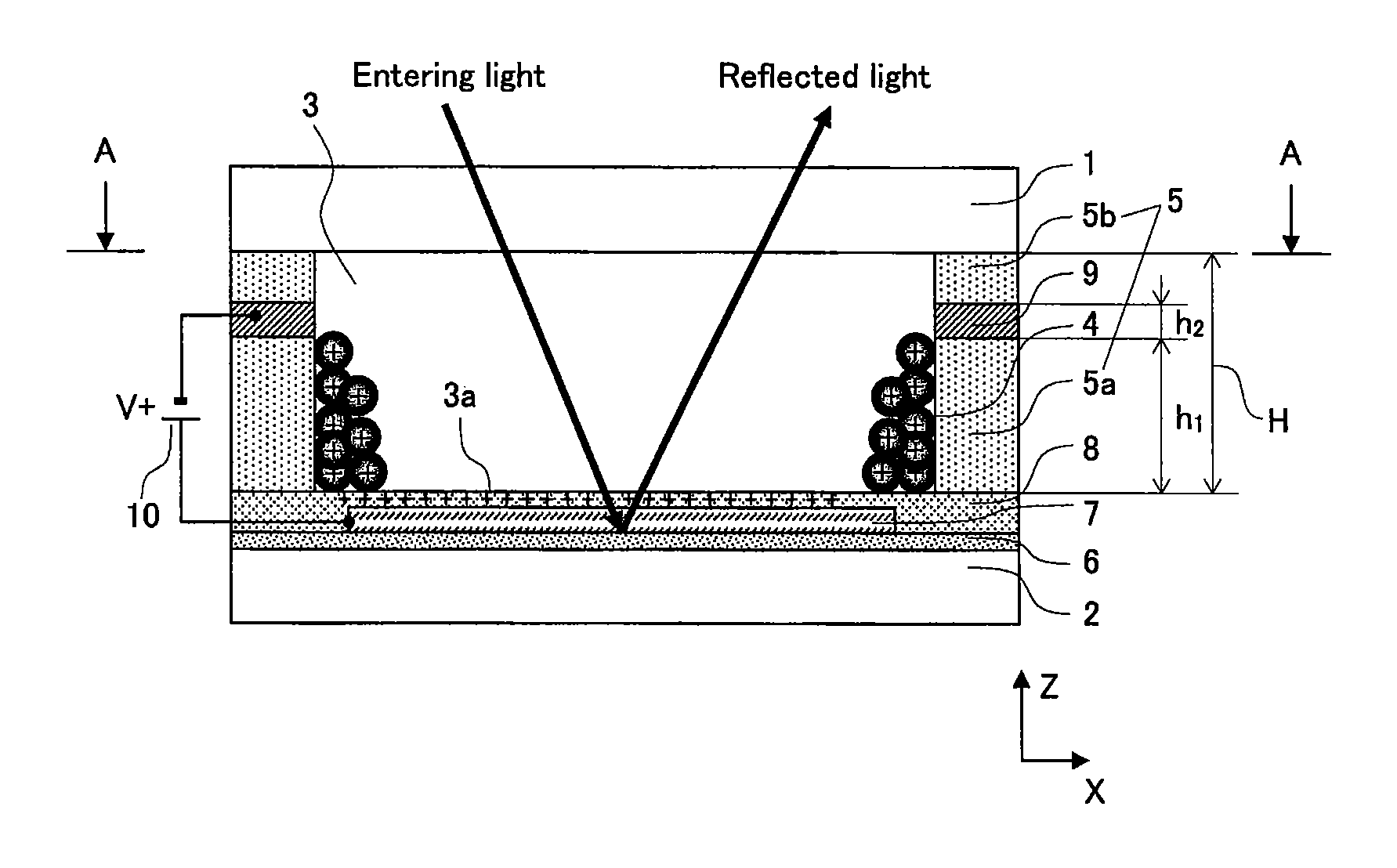
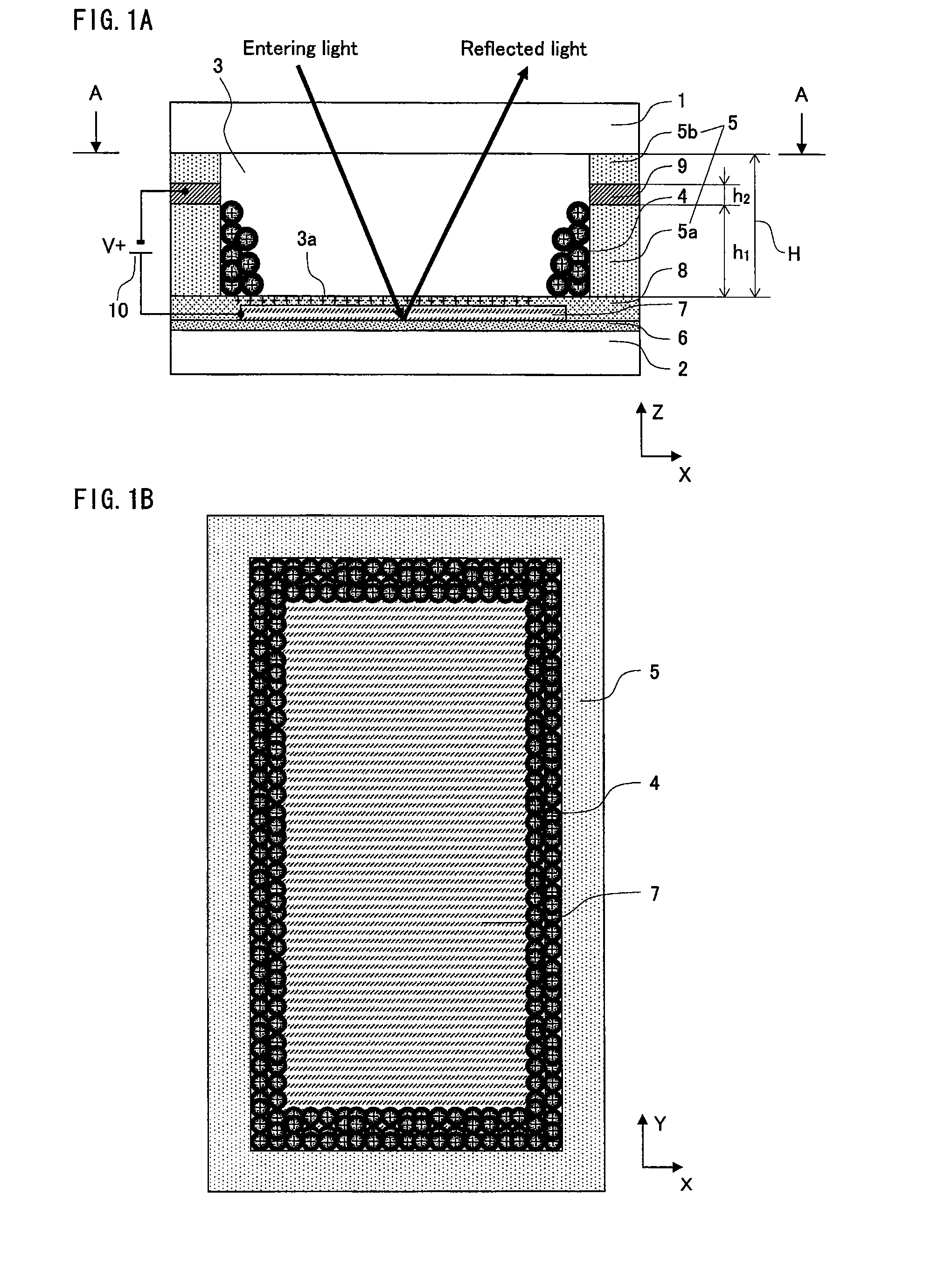
[0220]A display device according to the present embodiment is composed of a driving unit 10 and a display panel 100, in which a plurality of pixels are arranged in a matrix along the horizontal direction (X direction) and the vertical direction (Y direction).
[0221]The following describes the device structure of the display panel 100.
[0222]FIG. 1A is a partial cross-section diagram showing the structure of the display panel according to Embodiment 1-1, illustrating a representative pixel (unit of display).
[0223]The following describes a display panel in which each pixel displays black or white. A full-color display panel can also be achieved, however, by structuring each pixel to have sub-pixels that are red (R), green (G), and blue (B), or cyan (C), yellow (Y), and magenta (M).
[0224]An example of the size of each pixel is a pitch of 300 μm in both the horizontal direction (X direction) and vertical direction (Y direction). In the case of a full-color display, each of the red (R), gr...
example 1
[0288]The following describes an example of a method of manufacturing the display panel 100.
Manufacturing the Back Substrate 2
[0289]The white reflective layer 6, which is formed from a titanium oxide (titania) film, is coated, printed, cold sprayed, or the like on the back substrate 2, which is formed from alkalifree glass, so as to be formed on the surface necessary for image display, i.e. almost the entire surface of the substrate except for the peripheral portion thereof.
[0290]Next, a thin film is formed from ITO, which is a transparent conductive material, by sputtering, vapor deposition, or the like, and a predetermined rectangular shape is patterned by a process such as lithography or etching in order to form the first electrode 7. Polycarbonate charge transport material that is dissolved in a solvent is then coated or printed to form the insulating layer 8 on almost the entire substrate, except for the peripheral portion thereof. The surface-treated layer 8b, having protrusio...
modification to example 1
[0328]In Example 1 shown in FIG. 1, the dimensions of the first electrode 7 are set to fit within the region of the cell space 3 on the inner side of the partition walls 5. As in the example shown in FIG. 21, however, the first electrode 7 may be formed to extend beyond the region of the cell space 3, so that in plan view from the front of the panel, the outer periphery of the first electrode 7 overlaps the second electrode 9.
[0329]In this modification, as in the display panel 100 in FIG. 1, a uniform electrical field forms along the side of the partition walls 5. Since the electric energy density grows higher, however, the driving voltage may be lowered. This advantageous effect is similar to the advantageous effect of forming the second electrode 9 to project from the side of the partition walls 5 as described below in Embodiment 1-2.
PUM
| Property | Measurement | Unit |
|---|---|---|
| thickness | aaaaa | aaaaa |
| thickness | aaaaa | aaaaa |
| size | aaaaa | aaaaa |
Abstract
Description
Claims
Application Information
 - R&D
- Intellectual Property
- Life Sciences
- Materials
- Tech Scout
- Unparalleled Data Quality
- Higher Quality Content
- 60% Fewer Hallucinations
Browse by: Latest US Patents, China's latest patents, Technical Efficacy Thesaurus, Application Domain, Technology Topic, Popular Technical Reports.
© 2025 PatSnap. All rights reserved.Legal|Privacy policy|Modern Slavery Act Transparency Statement|Sitemap|About US| Contact US: help@patsnap.com


