Charged particle beam apparatus
a charge-pulverized particle and beam technology, applied in the direction of magnetic discharge control, beam deviation/focusing by electric/magnetic means, instruments, etc., can solve the problems of difficult to separate the generated aberration and the tilt angle from each other, and achieve the effect of simple structur
- Summary
- Abstract
- Description
- Claims
- Application Information
AI Technical Summary
Benefits of technology
Problems solved by technology
Method used
Image
Examples
first embodiment
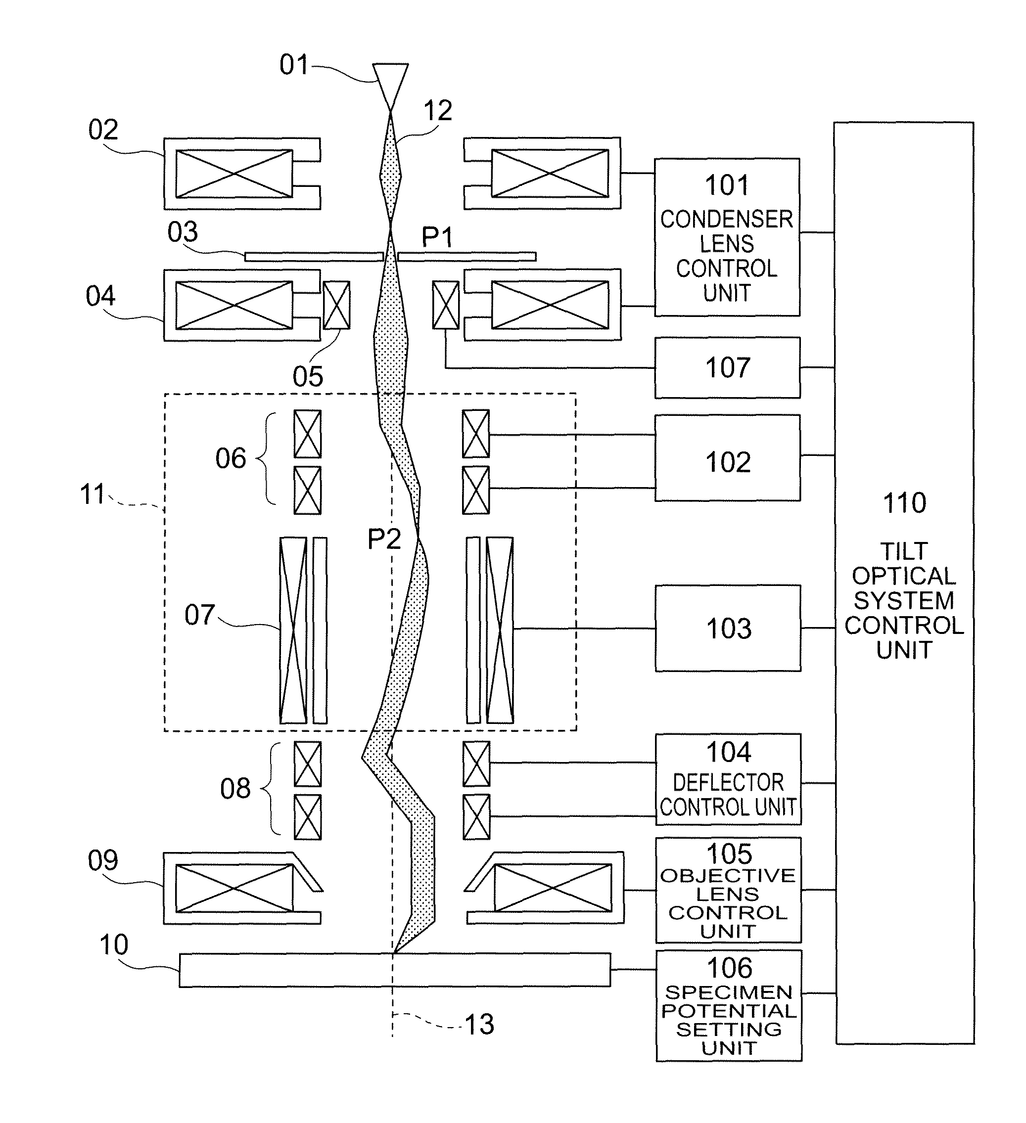
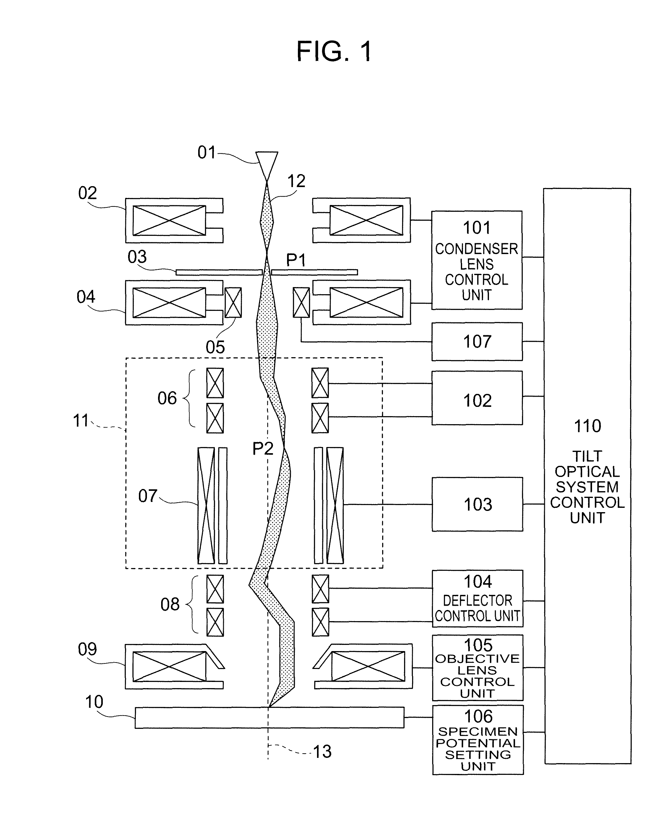
[0041]Embodiments are described in detail below with reference to the drawings. The structure of the first embodiment is shown in FIG. 1, a flowchart is shown in FIG. 4, and details of a tilt optical system control unit 110 are shown in FIG. 5. In Step 001, excitation conditions for each lens and a specimen potential are given to a condenser lens control unit 101, an objective lens control unit 105 and a specimen potential setting unit 106 and set by the tilt optical system control unit 110. (In this embodiment, as an excitation amount of the condenser lens 04, P2 is explained referring to the conditions determined at the Wien filter inlet, but an aberration for correcting can be generated by the aberration correction unit 11 on the same principle even when P2 is set at another place in order to adjust the aperture angle and the current amount.) The tilt angle of the beam is set in Step 002. At this time, current for operating a deflection coil 8 according to the tilt angle is appli...
second embodiment
[0048]In Step 009, distortion aberration generated in the aberration correction unit 11 is corrected by the two-stage deflector 08. Details of the correction method are described in a In Step 010, the beam is tilted with superimposing the correction amount of the distortion aberration determined in Step 009 on the deflection coil 08. In Step 011, an SEM image when the beam was tilted is obtained.
[0049]In Step 012, a tilt image of the beam is obtained, and it is judged if a desired sharpness degree was obtained from the sharpness degree of the image. If the desired sharpness degree was not obtained, the process returns to Step 007 to give a new Δrp2.
[0050]In this embodiment, the operation condition stored in the operation condition recording units (211, 212 and 213) are used when the beam is tilted, so that the adjustment procedure performed when the beam is tilted can be made simple.
[0051]As the second embodiment, a method of correcting the distortion aberration generated by the co...
third embodiment
[0057]As a third embodiment, description is made on a beam tilt optical system which can simultaneously generate a dispersion and coma aberration when another stage of the Wien filter is added instead of the deflector 06 without giving a change of entry position Δrp2 to the Wien filter 07.
[0058]FIG. 7 shows a structure diagram of the beam tilt optical system according to this embodiment. The aberration correction unit 11 of the beam tilt optical system shown in the first and second embodiments is comprised of a combination of the deflector and the Wien filter, but an aberration correction unit 14 according to this embodiment has a feature that it is comprised of a two-stage Wien filter.
[0059]Features of the aberration correction unit 11 and the aberration correction unit 14 are described. When the primary electrons 12 pass through the Wien filter 07 which is disposed in the aberration correction units (11 and 14), opening components (∝α*2 and ∝αα*) of the secondary aberration are ge...
PUM
 Abstract
Description
Claims
Application Information
 - R&D
- Intellectual Property
- Life Sciences
- Materials
- Tech Scout
- Unparalleled Data Quality
- Higher Quality Content
- 60% Fewer Hallucinations
Browse by: Latest US Patents, China's latest patents, Technical Efficacy Thesaurus, Application Domain, Technology Topic, Popular Technical Reports.
© 2025 PatSnap. All rights reserved.Legal|Privacy policy|Modern Slavery Act Transparency Statement|Sitemap|About US| Contact US: help@patsnap.com


