
Method for weighing products and a checkweigher with roller assemblies that dampen the movement of the produce prior to weighing

a technology of roller assemblies and checkweighers, which is applied in the direction of weighing apparatus for continuous material flow, instruments, transportation and packaging, etc., can solve the problems of inaccurate weight readings and inaccuracy of consecutive product weight readings, so as to minimize the total weight measured by the weighing cell, minimize the interference caused by vibration, and improve the effect of accuracy

Active Publication Date: 2014-05-06
NORDEN MASCH AB
View PDF11 Cites 8 Cited by
  • Summary
  • Abstract
  • Description
  • Claims
  • Application Information

AI Technical Summary

Benefits of technology

[0022]The solution also prevents the weighing cell from being subjected to an initial spike load caused by the transfer mechanism depositing the products on the checkweigher. Although the displacement of the product from the first to the second position will cause an initial load transient in the output signal from the weighing cell, this load transient is considerably smaller than said spike load. The time required for completing a weighing cycle can therefore be reduced. The weighing cycle may be reduced further by processing the output signal from the weighing cell using commercially available software. The use of suitable software may reduce the effect of load transients further. This may allow for a relatively high production speed or an increase in production speed with maintained accuracy. In this context, a relatively high production speed is considered to be in the region of 100 products per minute or higher. For example, a checkweigher handling two products at the time and being operated at a production speed of 200 products per minute, may have a weighing cycle of approximately 250 ms or less and the actual weighing process may take in the region of 50-60 ms. In this context, a weighing cycle is the period of time taken from the placing of a product on the checkweigher by a transfer mechanism until its removal there from by the same or a further transfer mechanism. The accuracy of the weighing cell is dependent on the type and capacity of weighing cell, which is in turn selected dependent on the weight range of the product or products to be handled by the production line.
[0024]In order to minimize interference caused by vibration from the production line or the driving mechanism for the first supports from disturbing the weighing of the products, the checkweigher may be mounted on a separate machine stand. Also, the displacement of the first support may be achieved using a drive means mounted separate from the checkweigher. This may be done by mounting the driving mechanism for the first supports on the machine stand of an adjacent transfer mechanism. When displacing the first support relative to the second support it is also desirable to maintain the first and second supports out of contact with each other at all times.
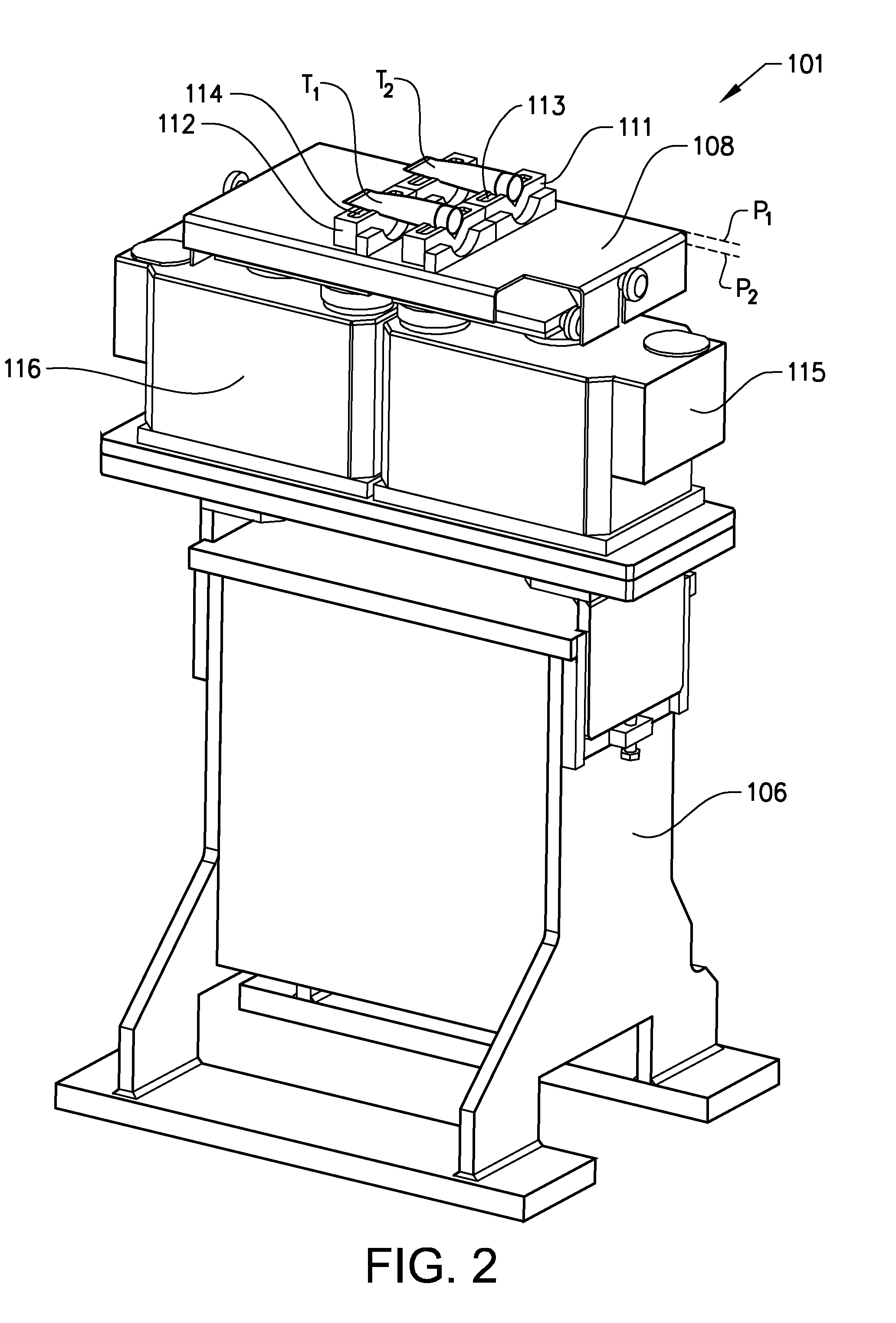
[0027]The first support is mounted out of contact with the second support in both the first and second positions as well as during the displacement of the first support. This can be achieved by arranging each first support is arranged side-by-side with a corresponding second support. Alternatively, at least a portion of each second support can be arranged to extend through the first support. In this way a product supporting upper surface of the second support may extend above the product supporting upper surface of the first support. Because the weighing cell is only required to support each product and its second support, the weight of the at least one first support to be eliminated. In this way the total weight measured by the weighing cell can be minimized and the accuracy is improved.
[0028]In order to minimize interference caused by vibration from the production line or the driving mechanism for the first supports from disturbing the weighing of the products, the checkweigher may be mounted on a separate machine stand. Also, the drive means for the displacement of the first support can be mounted separate from the checkweigher. The first support may for instance be mounted on a displaceable frame connected to the driving mechanism for displacing the first supports. The displaceable frame and the driving mechanism may be mounted on the machine stand of an adjacent transfer mechanism. When displacing the first support relative to the second support it is also desirable to maintain the first and second supports out of contact with each other at all times.
[0029]Each of the first and second supports are provided with upper contact surfaces corresponding to a contacting surface on the products to be weighed. The main purpose of the upper contact surfaces is to allow the products to be placed on the checkweigher in a predetermined position and to prevent movement of the products during any subsequent displacement. The upper contact surfaces will maintain each product in this position during the weighing procedure and during the subsequent removal of the products. For this reason the upper contact surfaces of the first and second supports will as a rule have the same or at least similar shapes. However, the shapes of the respective upper surfaces is determined by the shape of the product and / or the relative positioning of the first and second supports. In order to allow the checkweigher to handle products being within the weight range of the weighing cells, but having a different size or shape, the first and second supports may be replaceable. In this way it is possible to exchange a set of first and second supports having a first shape with a set of first and second supports having a second shape.
[0030]A first support, as described above, may be attached to a support plate extending over the upper surface of the at least one weighing cell in the horizontal plane. If more than one weighing cell is used, then the support plate may extend over the upper surface of all weighing cell. In addition, the support plate may extend a predetermined distance in the vertical plane below said upper surface around at least part of the periphery of the support plate. In addition to provide a means for attaching replaceable first supports, the support plate also serves to protect at least the upper portion of the weighing cells. The horizontal, upper portion prevents products, leaking substances or any parts of the transfer mechanism from direct or accidental contact with the weighing cells. In addition, the horizontal, upper portion and the vertical, circumferential portion minimizes the effect of turbulence created by rapidly moving transfer mechanisms from interfering with the weighing process.

Problems solved by technology

However, such an arrangement may often result in inaccurate readings, especially if the product is moving or if it is not stopped in the exact position required for weighing.
Also, if an interruption occurs in the production the synchronization of the position of a stopped product relative to a checkweigher may not coincide with the desired position for weighing.
An additional problem is that adjacent products may not be correctly spaced, resulting in inaccurate weight readings for consecutive products.

Method used


Image

  • Method for weighing products and a checkweigher with roller assemblies that dampen the movement of the produce prior to weighing
  • Method for weighing products and a checkweigher with roller assemblies that dampen the movement of the produce prior to weighing
  • Method for weighing products and a checkweigher with roller assemblies that dampen the movement of the produce prior to weighing

Examples


Embodiment Construction

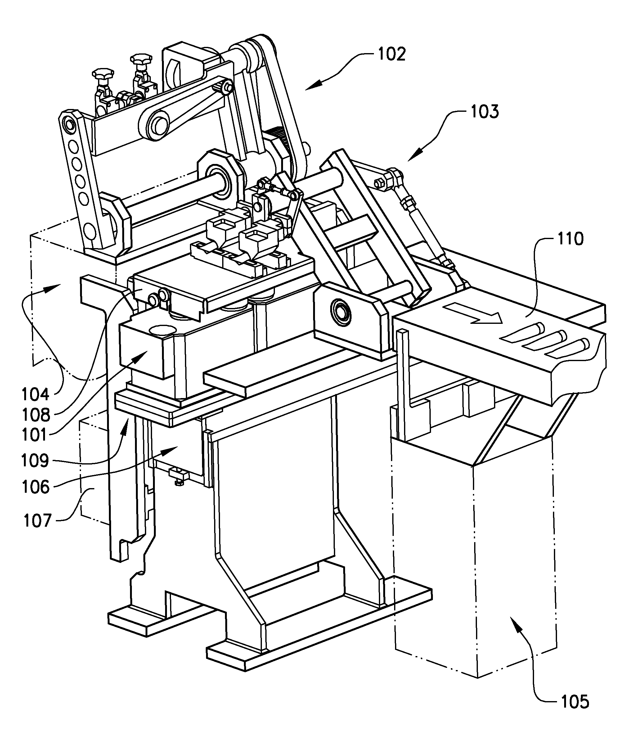
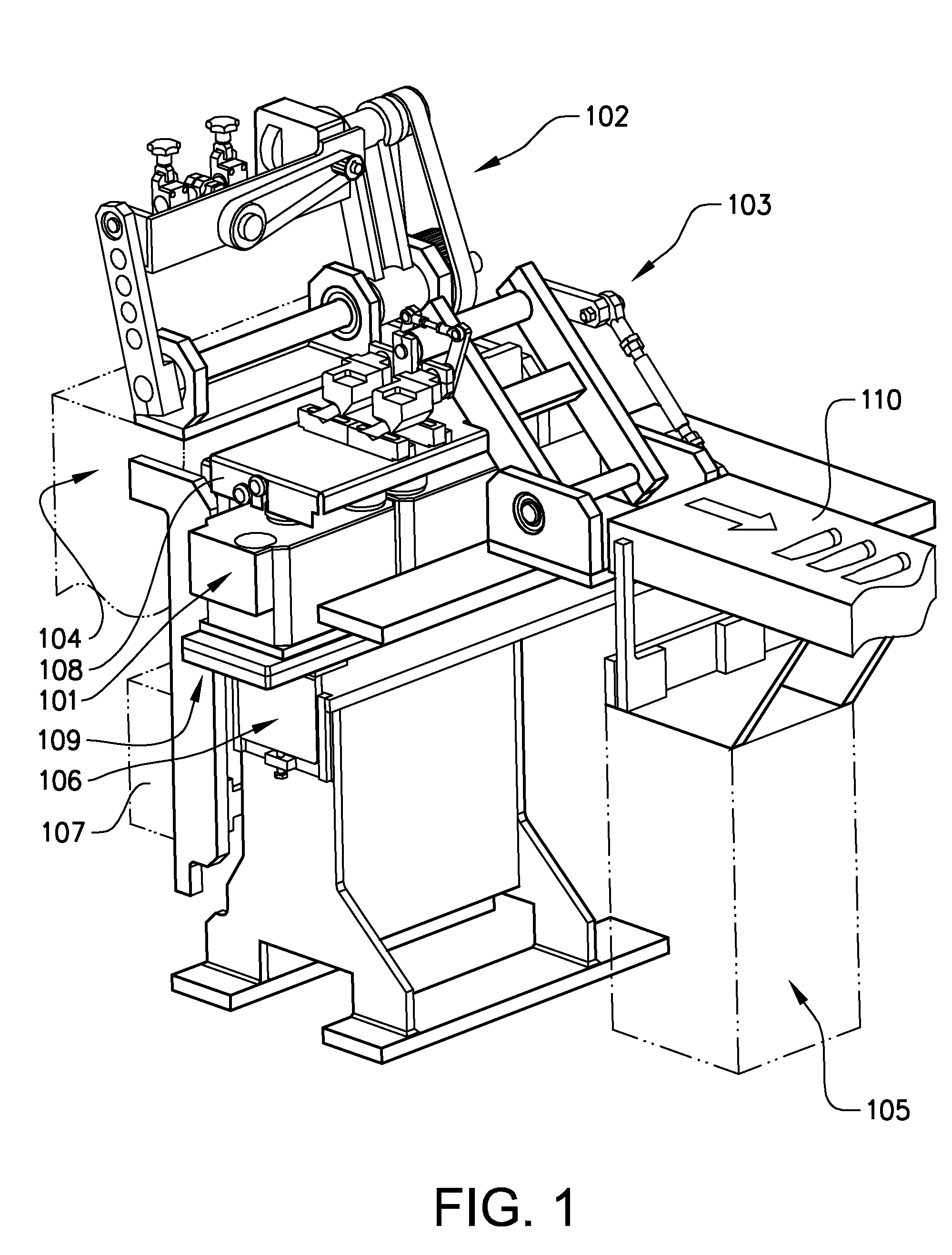
[0042]FIG. 1 schematically illustrates a part of a production line with a checkweigher according to the invention. In this example the checkweigher 101 is located between a filling station and a packaging station (not shown) in a production line for filling and packaging tubes, such as tubes for toothpaste or cosmetic products. The checkweigher in FIG. 1 is located between a first pick-and-place device 102 and a second pick-and-place device 103. The first pick-and-place device 102 is arranged to pick filled tubes arranged in a vertical position from a filling conveyor (not shown), rotate the tubes through an angle of 90° and place the tubes in a horizontal position on the checkweigher 101. The second pick-and-place device 103 is arranged to pick tubes from the horizontal position on the checkweigher 101 and place the tubes in a horizontal position on a subsequent conveyor 110 for transfer to a packaging station. Both the first and the second pick-and-place device 102, 103 are mounte...


PUM


Abstract

Embodiments of the invention relate to a method and a checkweigher for weighing individual products moved along a production line. In various embodiments, the method compromises transferring at least one product from the production line to a checkweigher comprising at least one weighing cell; placing at least one product in a first position on a first support above a corresponding weighing cell; displacing the at least one product by means of said first support and placing said at least one product in a second position on a second support on the weighing cell; weighing the at least one product; displacing the at least one product back to the first position by means of said first support; and transferring the at least one product from the checkweigher back to the production line.

Description

RELATED APPLICATIONS[0001]This application is a nationalization under 35 U.S.C. 371 of PCT / SE2010 / 050270, filed Mar. 10, 2010 and published as WO 2010 / 104465 A1 on Sep. 16, 2010, which claims priority to Sweden Patent Application No. 0900309-6, filed Mar. 10, 2009; which applications and publication are incorporated herein by reference in their entirety.TECHNICAL FIELD[0002]The invention relates to the technical field of weighing individual products being moved along a continuous production line, which products are moved along the production line by at least one transfer mechanism.BACKGROUND ART[0003]In a continuous production line wherein a substance in liquid, semi-liquid or pasty form may be filled into containers it is desirable to monitor the quantity of the substance filled into each container. Prior art checkweighers have often been placed in or under a conveyor transferring the filled product from a filling station to a station for subsequent processing, such as packaging.[0...

Claims


Application Information

Patent Timeline
Patent Type & Authority Patents(United States)
IPC IPC(8): B65G47/00G01G11/00
CPCG01G15/00
Inventor KARLSSON, ANDERSNILSSON, JAN
Owner NORDEN MASCH AB
Learn More