
System and method to define a rotational source associated with a biological rhythm disorder

a biological rhythm disorder and system technology, applied in the field of biological rhythm disorders, can solve the problems of significant morbidity and death in the world, difficult treatment of heart rhythm disorders, and failure to achieve the effect of complex rhythm disorders

Active Publication Date: 2014-05-06
TOPERA
View PDF79 Cites 40 Cited by
  • Summary
  • Abstract
  • Description
  • Claims
  • Application Information

AI Technical Summary

Benefits of technology

The present patent is about a system and method for identifying and treating rhythm disorders in the heart and other biological systems. It uses reconstructed cardiac activation information to determine the core of the rotational source causing the disorder and can quickly and accurately treat it. This approach helps to eliminate the heart rhythm disorder and spare the destruction of healthy heart tissue. Overall, the invention provides a precise and efficient tool for identifying and treating biological rhythm disorders.

Problems solved by technology

Heart (cardiac) rhythm disorders are common and represent significant causes of morbidity and death throughout the world.
Previously, treatment of heart rhythm disorders—particularly complex rhythm disorders of AF, VF and polymorphic VT—has been difficult because the location in the heart that harbors the source of the heart rhythm disorder could not be identified.
However, none of the applications proved fruitful in the treatment of complex rhythm disorders.
There are no known systems or methods to define a rotational source associated with a heart rhythm disorder, including a rotational path and a likely center of rotation associated with the rotational source.

Method used


Image

  • System and method to define a rotational source associated with a biological rhythm disorder
  • System and method to define a rotational source associated with a biological rhythm disorder
  • System and method to define a rotational source associated with a biological rhythm disorder

Examples


Embodiment Construction

[0041]A system and method to define a rotational source of a biological rhythm disorder, such as a heart rhythm disorder, is disclosed herein. In the following description, for the purposes of explanation, numerous specific details are set forth in order to provide a thorough understanding of example embodiments or aspects. It will be evident, however, to one skilled in the art, that an example embodiment may be practiced without all of the disclosed specific details.

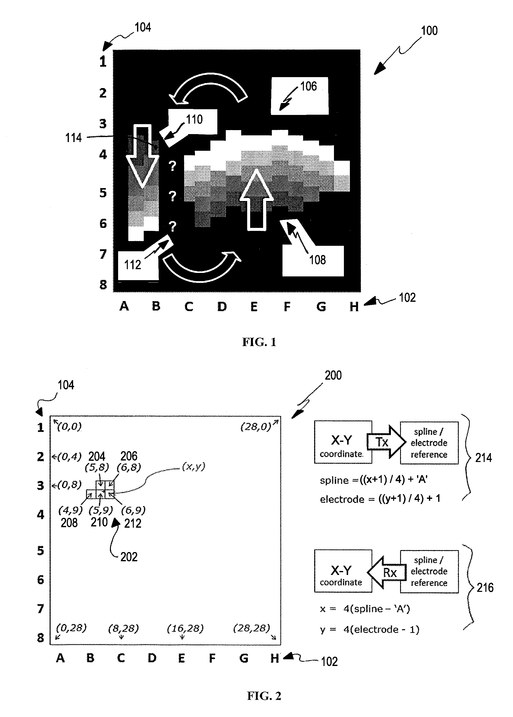
[0042]FIG. 1 illustrates an example graphical mapping 100 of an example rotational source 106 associated with a heart rhythm disorder in a patient. For example, the rotational source 106 is a source of a heart rhythm disorder in a right atrium of the patient's heart that is observed to progress in a counter-clockwise rotational pattern about a subjective rotation center 112 (one or more of the locations marked with question marks), which can be evaluated by a physician to be along the electrode reference 104, anywhere b...


PUM


Abstract

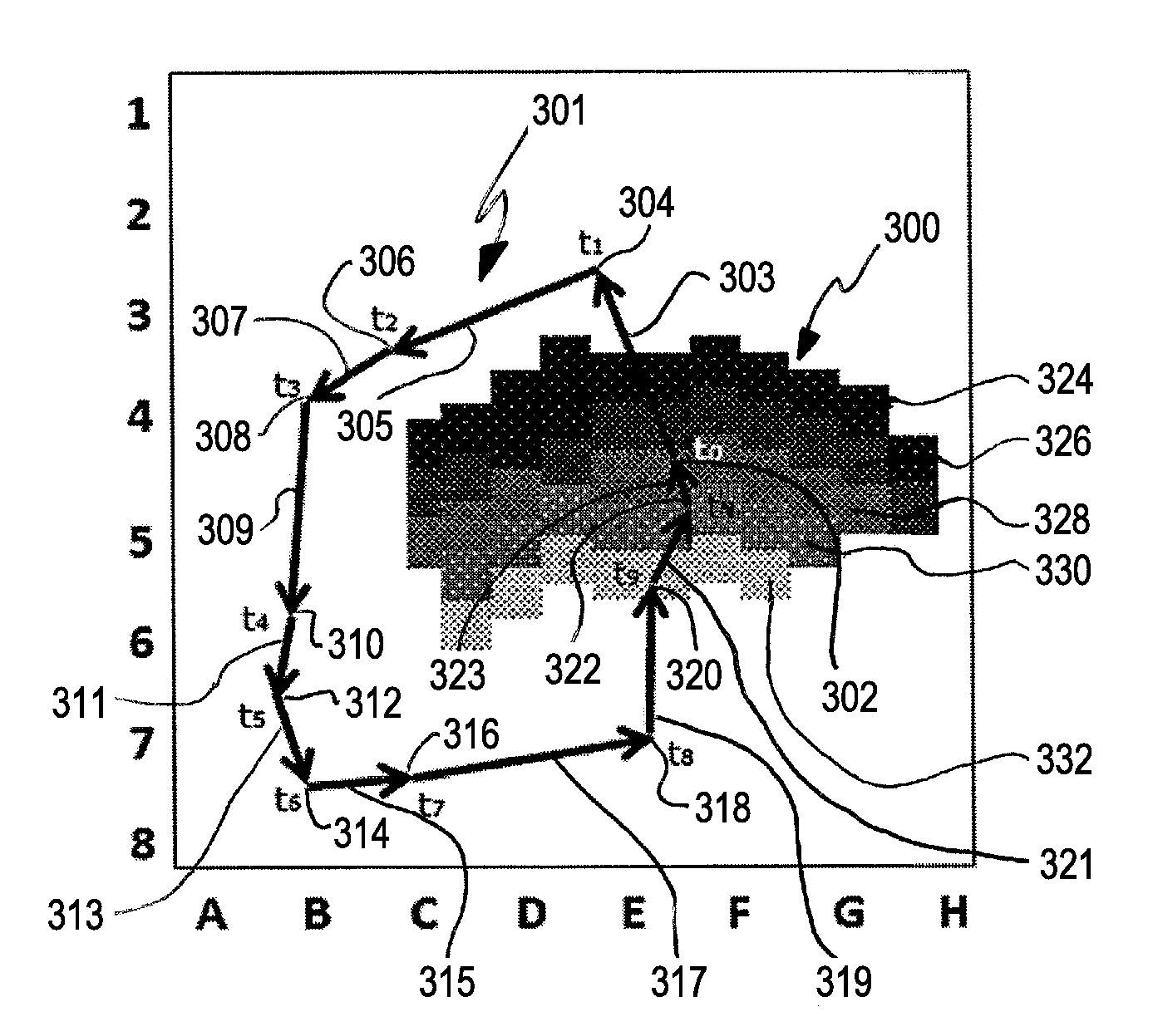
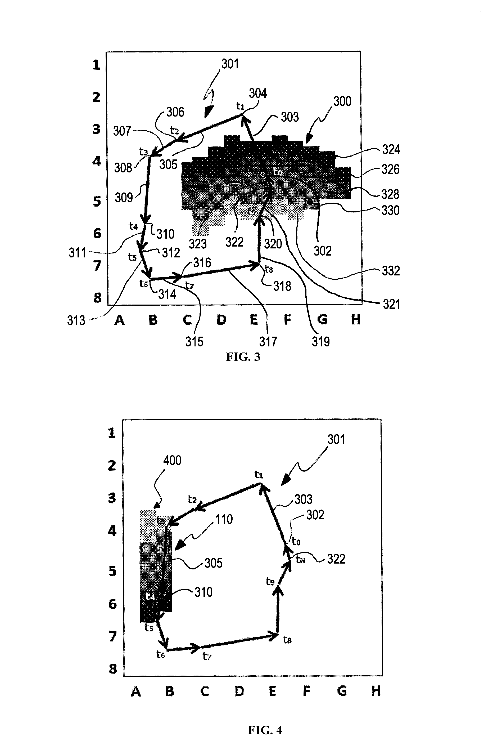
An example system and method of defining a rotational source associated with a heart rhythm disorder are disclosed. A plurality of center locations of wave fronts are calculated at a plurality of time points associated with the heart rhythm disorder. A rotational path that connects the plurality of center locations is then determined. The system and method can also determine a likely core associated with the rotational path. A plurality of relative diffusion shapes associated with the plurality of the center locations is calculated. A plurality of intersecting points of a smallest relative diffusion shape and other relative diffusion shapes is determined within the rotational path. A bounded polygon of the intersecting points is defined as the likely core.

Description

BACKGROUND[0001]1. Field[0002]The present application relates generally to biological rhythm disorders. More specifically, the present application is directed to a system and method to define a rotational source associated with a biological rhythm disorder, such as a heart rhythm disorder.[0003]2. Brief Discussion of Related Art[0004]Heart (cardiac) rhythm disorders are common and represent significant causes of morbidity and death throughout the world. Malfunction of the electrical system in the heart represents a proximate cause of heart rhythm disorders. Heart rhythm disorders exist in many forms, of which the most complex and difficult to treat are atrial fibrillation (AF), ventricular tachycardia (VT) and ventricular fibrillation (VF). Other rhythm disorders are more simple to treat, but may also be clinically significant including atrial tachycardia (AT), supraventricular tachycardia (SVT), atrial flutter (AFL), supraventricular ectopic complexes / beats (SVE) and premature vent...

Claims


Application Information

Patent Timeline
IPC IPC(8): A61B5/04
CPCA61B5/044A61B5/04012A61B5/04011A61B5/0245G06K9/00A61B5/02405A61B5/04A61B5/0452G06K9/4604G06T7/0083G06T2207/30048A61B2576/023G06T7/12G16H30/40A61B5/341A61B5/316A61B5/287A61B5/339A61B5/349
Inventor MACNEIL, WILLIAM ROBERTSEHRA, RUCHIR
Owner TOPERA
Learn More