
Dual microphone EAS system that prevents feedback

a technology of eas system and microphone, applied in the field of hearing aid systems, can solve the problems of affecting hearing aid users, amplification hearing aid system becoming unstable and squealing, etc., and achieves the effect of eliminating unwanted feedback and removing the feedback within the hearing aid portion of the eas system

Inactive Publication Date: 2014-04-15
ADVNACED BIONICS LLC
View PDF9 Cites 6 Cited by
  • Summary
  • Abstract
  • Description
  • Claims
  • Application Information

AI Technical Summary

Benefits of technology

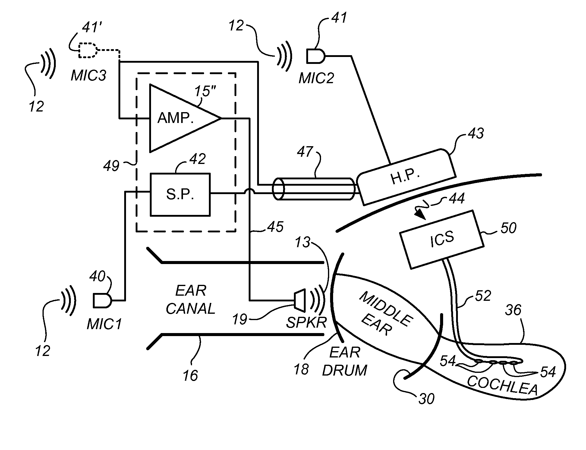
The present invention is a system that combines a hearing aid and a cochlear implant to provide better hearing experience for users. The hearing aid senses and amplifies low frequency acoustic sounds while the cochlear implant senses and stimulates the inner ear with electrical stimulation. The invention eliminates feedback within the hearing aid by positioning the microphone at a remote location, while the cochlear implant is placed at a location near the ear canal to better sense high frequency acoustic sounds. The technical effect of the invention is the elimination of feedback in the hearing aid and improved sensory experience for users.

Problems solved by technology

A common problem that plagues hearing aid users is feedback.
Feedback occurs in an acoustic amplification system, such as a hearing aid system, when the amplified sound is picked up by the microphone, causing the amplification system to become unstable and squeal.
However, despite efforts to seal the ear canal (e.g., by preparing an ear mold designed to fit tightly in the ear canal with the microphone held on the side of the mold facing the outside of the ear, and the speaker held on an opposite side of the mold facing the ear drum, with the intent of acoustically separating the speaker from the microphone), some acoustic sound waves broadcast from the speaker always seem to leak back to the microphone, where they are sensed by the microphone, causing the hearing aid system to become unstable and squeal.

Method used


Image

  • Dual microphone EAS system that prevents feedback
  • Dual microphone EAS system that prevents feedback
  • Dual microphone EAS system that prevents feedback

Examples


Embodiment Construction

[0020]The following description is of the best mode presently contemplated for carrying out the invention. This description is not to be taken in a limiting sense, but is made merely for the purpose of describing the general principles of the invention. The scope of the invention should be determined with reference to the claims.

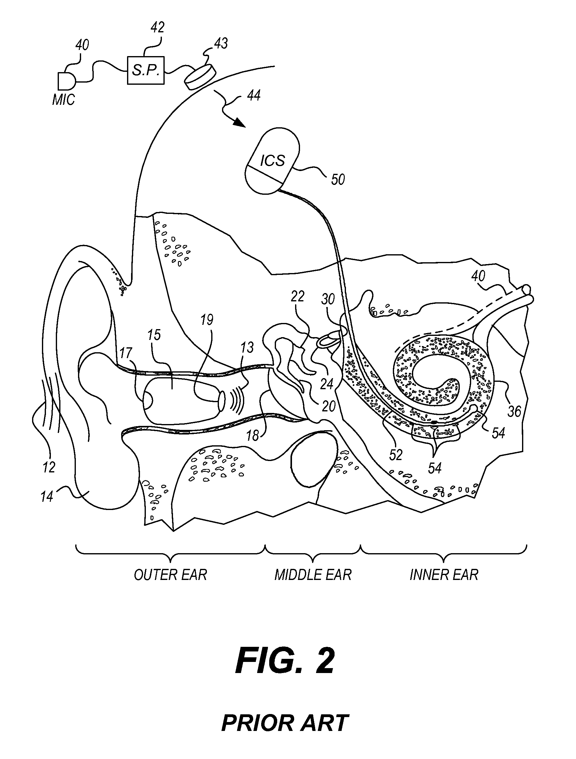
[0021]Turning first to FIG. 1, a system is depicted that uses electrical stimulation of the inner ear to enhance the perception of high frequency sounds, and residual hearing to sense low frequency sounds. The description of this hybrid system (using both electrical stimulation and residual hearing) is presented as background to better understand the operation of the dual microphone EAS system described in more detail below.

[0022]As seen in FIG. 1, the major relevant components of the outer, middle and inner ear are illustrated. To better understand the present invention, it will first be helpful to briefly review the normal operation of a fully functional e...


PUM


Abstract

An exemplary method includes an electro-acoustic stimulation (EAS) system associated with a user 1) processing sounds sensed by a first microphone coupled to a cochlear implant portion of the EAS system, 2) applying electrical stimulation representative of the sounds sensed by the first microphone by way of a plurality of electrode contacts located in a basal region of a cochlea of the user, 3) processing sounds sensed by a second microphone coupled to a hearing aid portion of the EAS system, 4) broadcasting, way of a speaker, amplified sound signals representative of the sounds sensed by the second microphone into an ear canal of the user, and 5) acoustically separating the second microphone from the speaker to avoid feedback within the hearing aid portion of the EAS system. Corresponding methods and systems are also disclosed.

Description

RELATED APPLICATIONS[0001]The present application is a continuation application of U.S. patent application Ser. No. 12 / 584,306 by Matthew I. Haller, filed on Sep. 3, 2009, and entitled “Dual Microphone EAS System That Prevents Feedback,” which application is incorporated herein by reference in its entirety.BACKGROUND INFORMATION[0002]The present invention relates to hearing aid systems, and more particularly to a hybrid or Electro Acoustic Stimulation (EAS) hearing aid system that combines a cochlear stimulator and a hearing aid to provide a hearing aid system that relies primarily on the cochlear stimulator portion of the system for being able to sense high frequency sounds, and that relies primarily on normal hearing processes, assisted as required by a hearing aid, for being able to sense lower frequency sounds. A representative hybrid or EAS hearing system is described, e.g., in U.S. Pat. No. 6,754,537, incorporated herein by reference in its entirety.[0003]A hybrid or EAS heari...

Claims


Application Information

Patent Timeline
Patent Type & Authority Patents(United States)
IPC IPC(8): H04R25/00
CPCA61N1/36032H04R25/456H04R25/405A61N1/36038
Inventor HALLER, MATTHEW, I.
Owner ADVNACED BIONICS LLC
Learn More