
Flat bottom fitting assembly

a technology for fittings and components, applied in the field of flat bottom fitting assemblies, can solve the problems of unproductive time involved in disconnecting and connecting a column (or other component), affecting the performance of the system, and affecting the quality of the system

Active Publication Date: 2014-04-15
IDEX HEALTH & SCI
View PDF24 Cites 21 Cited by
  • Summary
  • Abstract
  • Description
  • Claims
  • Application Information

AI Technical Summary

Benefits of technology

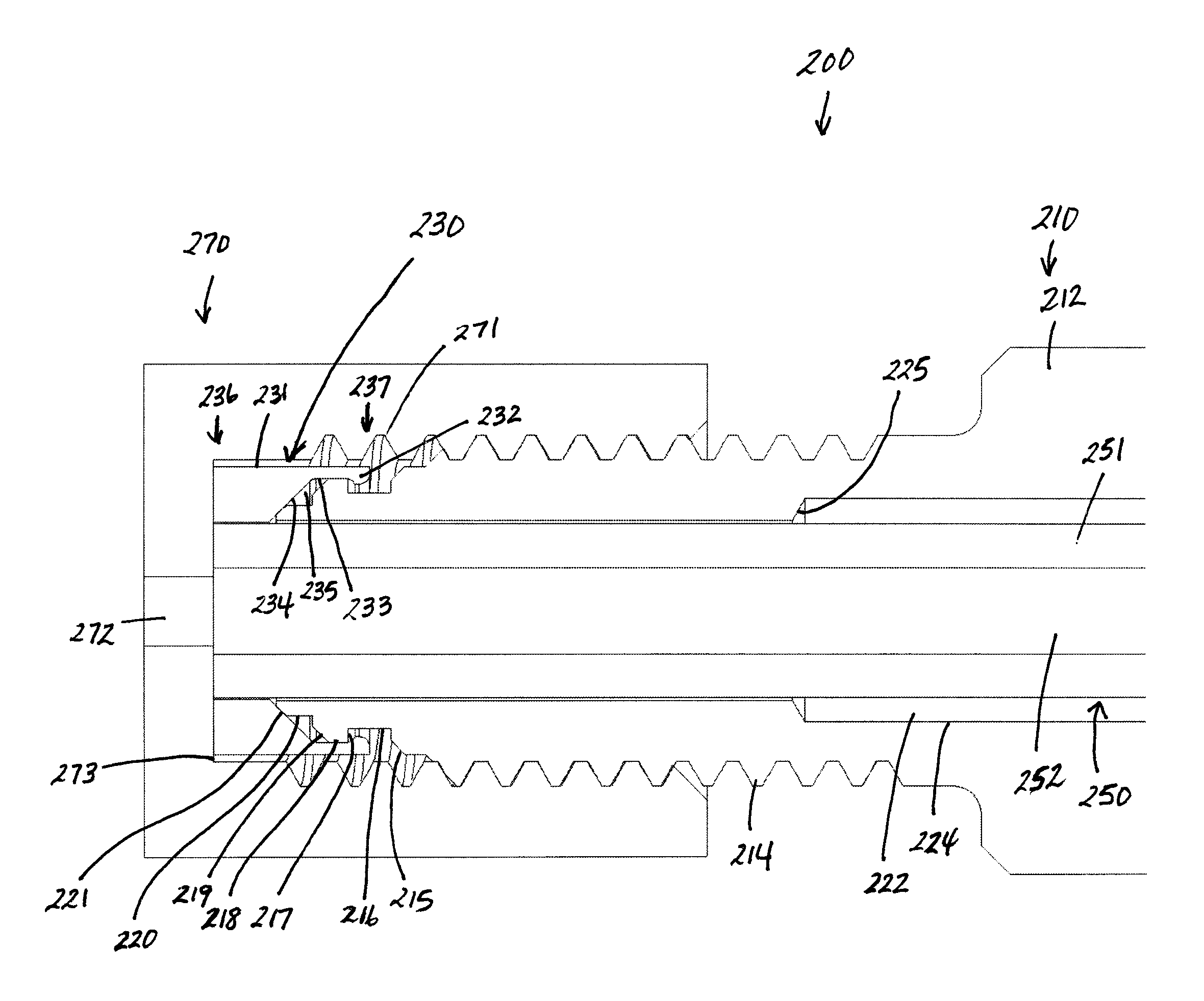
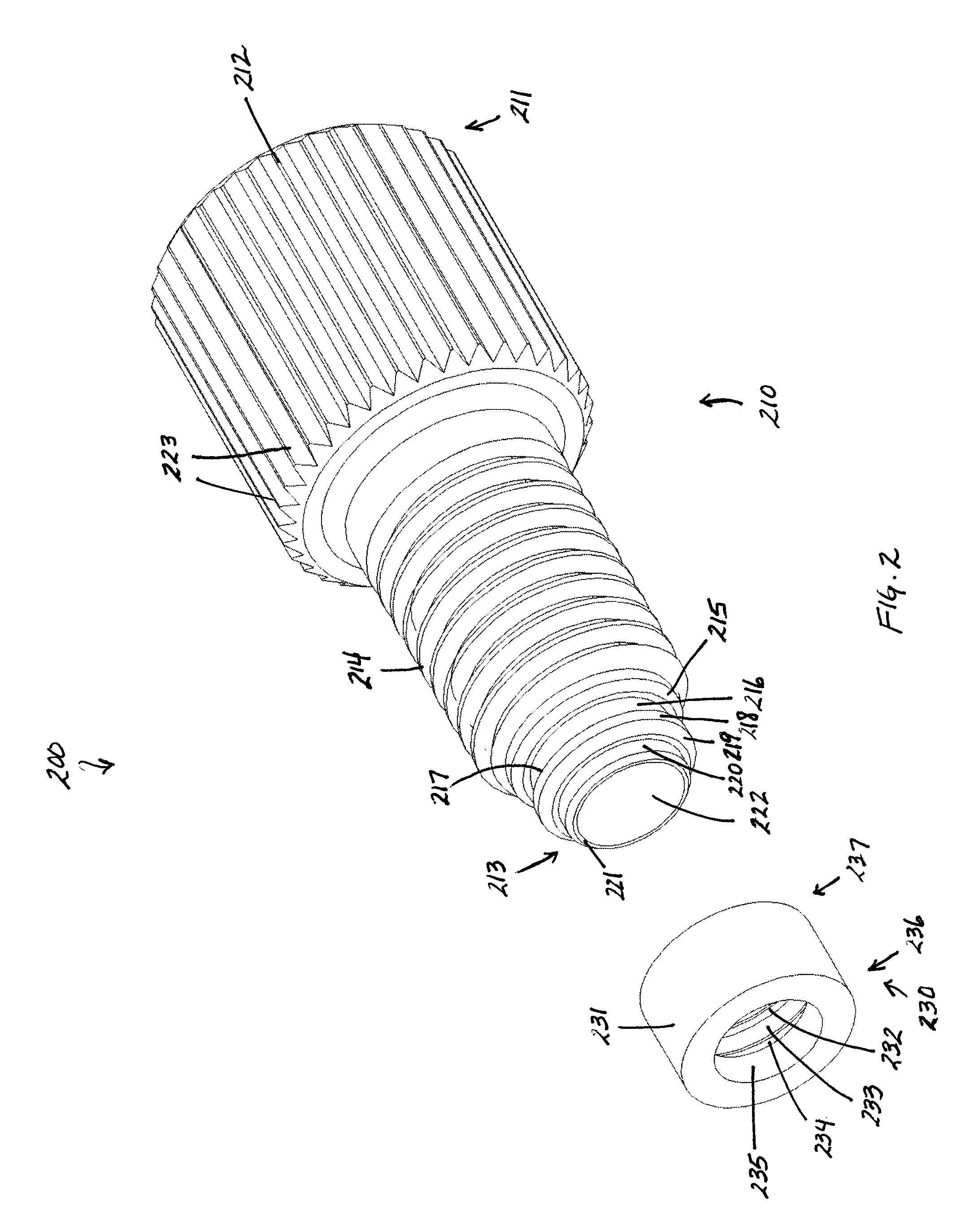
The present patent provides a fitting assembly for use in analytical instrument systems, particularly liquid chromatography and gas chromatography systems. The fitting assembly includes a nut and a ferrule with internally and externally tapered portions for securely engaging with each other. The nut has a passageway therethrough with a threaded portion and an external lip, while the ferrule has an internal lip and a passageway therethrough. The fitting assembly can be easily attached to the analytical instrument system without the use of tools. The technical effect of this invention is to provide a reliable and secure connection between tubing in the analytical instrument system and the fitting assembly, allowing for easy and safe attachment without the need for additional tools.

Problems solved by technology

Ion chromatography relies on the detection of ions in solution, so most metallic materials in the flow path can create interference in the detection scheme, as they create background ions.
If the connection is too weak, it may leak.
Because the types of solvents that are sometimes used as the mobile phase are often toxic and because it is often expensive to obtain and / or prepare many samples for use, any such connection failure is a serious concern.
Moreover, the time involved in disconnecting and then connecting a column (or other component) is unproductive because the LC system is not in use and the operator is engaged in plumbing the system instead of preparing samples or other more productive activities.
Hence, the replacement of a column in a conventional LC system involves a great deal of wasted time and inefficiencies.
More recently, however, it has been realized that the use of stainless steel components in a LC system have potential drawbacks in situations involving biological samples, and cannot be routinely used for ion chromatography.
This presents problems because the detector's measurements (and thus the chromatogram) of a given sample may not accurately reflect the sample if some of the sample's components or ions remain in the tubing and do not pass the detector.
Perhaps of even greater concern, however, is the fact that ions from the stainless steel tubing may detach from the tubing and flow past the detector, thus leading to potentially erroneous results.
One reason for this is that a valve having a large volume will contain a relatively large volume of liquid, and when a sample is injected into the valve the sample will be diluted, decreasing the resolution and sensitivity of the analytical method.
In addition, the use of such approaches to connect components of an LC system often results in deformation or swaging of a ferrule used to provide a leak proof seal of tubing to a fitting or component.
This often means that the ferrule and tubing connection, once made, cannot be reused without a risk of introducing dead volumes into the system.
In addition, such approaches may involve crushing or deformation of the inner diameter of the tubing, which may adversely affect the flow characteristics and the pressures of the fluid within the tubing.
Such an approach is considered undesirable because by requiring two places for the ferrules to provide leak proof seals, it provides two places where the fluid to be analyzed may leak, as well as where dead volumes may be provided.
In addition, this approach involves the use of additional components, which can cost more and also increase the time and effect to assemble them to make a connection or disassemble them when disconnecting tubing from a component or other fitting assembly.

Method used


Image

  • Flat bottom fitting assembly
  • Flat bottom fitting assembly
  • Flat bottom fitting assembly

Examples


Embodiment Construction

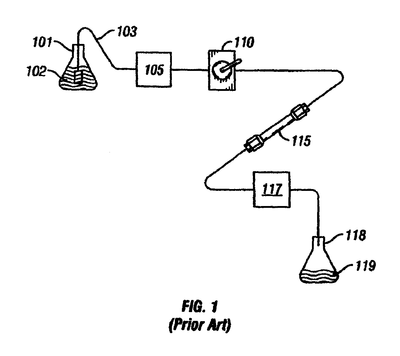
[0050]In FIG. 1, a block diagram of the essential elements of a conventional liquid chromatography (LC) system is provided. A reservoir 101 contains a solvent or mobile phase 102. Tubing 103 connects the mobile phase 102 in the reservoir 101 to a pump 105. The pump 105 is connected to a sample injection valve 110 which, in turn, is connected via tubing to a first end of a guard column (not shown). The second end of the guard column (not shown) is in turn connected to the first end of a primary column 115. The second end of the primary column 115 is then connected via tubing to a detector 117. After passing through the detector 117, the mobile phase 102 and the sample injected via injection valve 110 are expended into a second reservoir 118, which contains the chemical waste 119. As noted above, the sample injection valve 110 is used to inject a sample of a material to be studied into the LC system. The mobile phase 102 flows through the tubing 103 which is used to connect the variou...


PUM

PropertyMeasurementUnit
included angleaaaaaaaaaa

Abstract

A fitting assembly is provided having a nut and a ferrule, which in certain embodiments may be assembled by an operator. The nut and ferrule of the fitting assembly have passageways therethrough for receiving and removably holding tubing. The nut and ferrule fitting assembly may be adapted for use with a flat bottom port, such as in an analytical instrument, like liquid chromatography, gas chromatography, ion chromatography, or in in vitro diagnostic systems.

Description

CROSS-REFERENCE TO RELATED APPLICATION[0001]Not ApplicableSTATEMENT REGARDING FEDERALLY SPONSORED RESEARCH OR DEVELOPMENT[0002]Not ApplicableTHE NAMES OF THE PARTIES TO A JOINT RESEARCH AGREEMENT[0003]Not ApplicableINCORPORATION-BY-REFERENCE OF MATERIAL SUBMITTED ON A COMPACT DISC[0004]Not ApplicableBACKGROUND OF THE INVENTION[0005]1. Field of the Invention[0006]This invention relates generally to an assembly for use in connecting tubing and other components of gas chromatography, liquid chromatography, in vitro diagnostic analysis systems, environmental (water) analysis systems, and other analytical systems, and relates more particularly to a reusable assembly well-suited for allowing quick connections and disconnections of tubing and other components in analytical systems.[0007]2. Description of the Related Art[0008]Liquid chromatography (LC), ion chromatography (IC) and gas chromatography (GC) are well-known techniques for separating the constituent elements in a given sample. In...

Claims


Application Information

Patent Timeline
Patent Type & Authority Patents(United States)
IPC IPC(8): F16L19/06
CPCF16L19/00B01L2300/0838B01L3/563F16L15/04G01N30/6026G01N30/6004B01L3/565G01N30/6039Y10T29/49947
Inventor NIENHUIS, NATHANIEL
Owner IDEX HEALTH & SCI
Learn More