
Method for the spatially resolved measurement of parameters in a cross section of a beam bundle of high-energy radiation of high intensity

a high-energy radiation and cross-sectional technology, applied in the direction of optical radiation measurement, photometry using electric radiation detectors, instruments, etc., can solve the problems of only achieving a spatial resolution, high radiation energy and intensities quickly lead to saturation or even destruction, and the use of optical attenuators such as absorption filters between radiation sources and sensors is also possible only to a limited extent, so as to reduce the intensity of the partial beam bundle passing through the opening, the effect of high intensity

Inactive Publication Date: 2014-04-01
USHIO DENKI KK
View PDF17 Cites 2 Cited by
  • Summary
  • Abstract
  • Description
  • Claims
  • Application Information

AI Technical Summary

Benefits of technology

This approach allows for highly spatially resolved measurement data acquisition within high-energy beam bundles, ensuring accurate intensity distribution measurements without impairing sensor accuracy due to radiation loading, thereby supporting precise machining processes.

Problems solved by technology

Depending on the way in which the sensors operate, the characteristic passes after a certain value of the input signal into a saturation state which is not suitable for measuring purposes.
When sensors are used for measuring purposes of this kind, e.g., for soft X-ray radiation (EUV), the high radiation energies and intensities quickly lead to saturation or even destruction, e.g., due to high heat development in the sensors.
The use of optical attenuators such as absorption filters between the radiation source and the sensor is also possible only to a limited extent because of high heat development.
However, this solution achieves only a spatial resolution in the dimension of the size of the apertures.
However, these measurement data of the beam bundle by way of the respective stripes are averaged values and therefore cannot yield intensity values with high point-by-point resolution.

Method used


Image

  • Method for the spatially resolved measurement of parameters in a cross section of a beam bundle of high-energy radiation of high intensity
  • Method for the spatially resolved measurement of parameters in a cross section of a beam bundle of high-energy radiation of high intensity
  • Method for the spatially resolved measurement of parameters in a cross section of a beam bundle of high-energy radiation of high intensity

Examples


Embodiment Construction

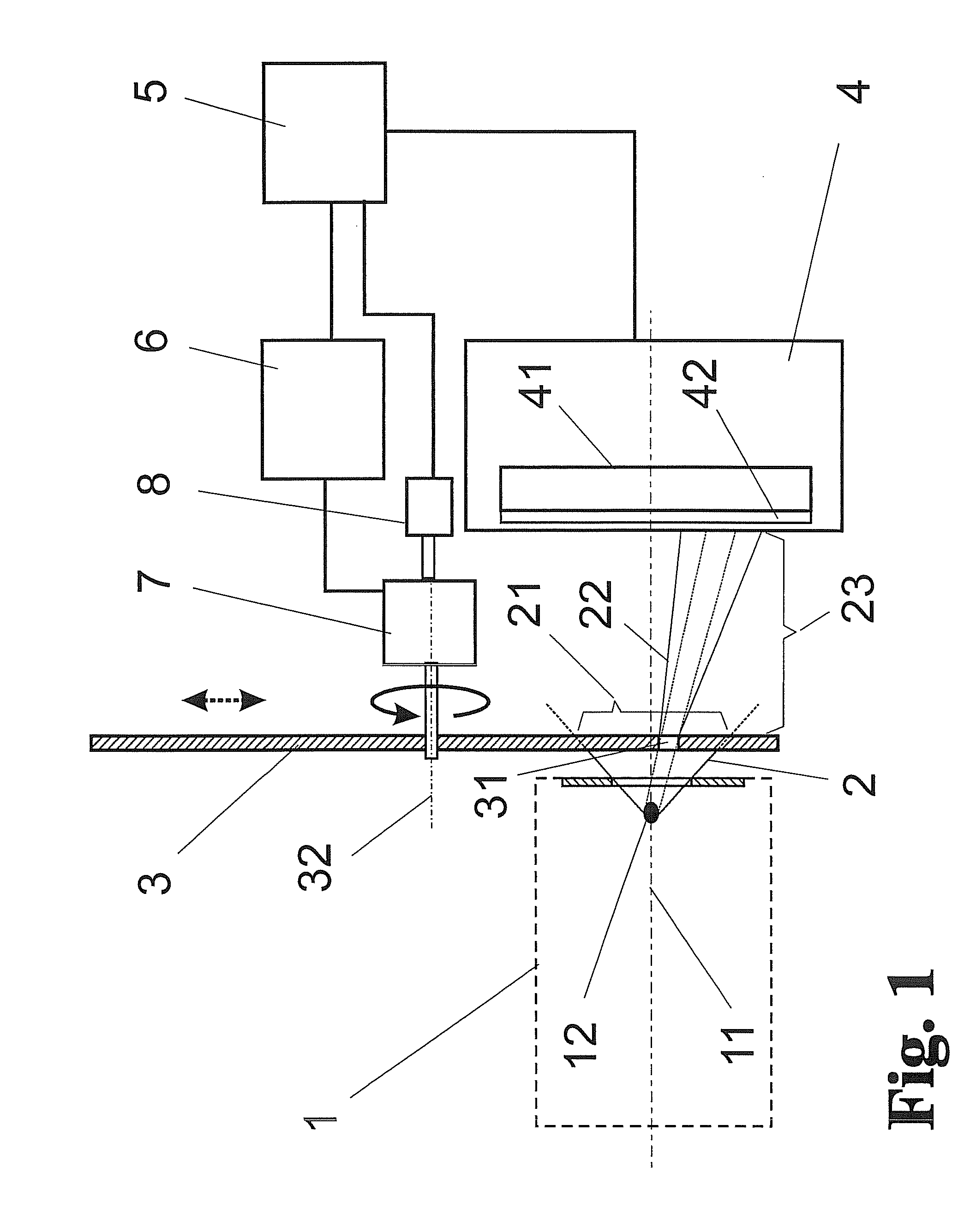
[0057]The method will be described with reference to the schematic construction shown in FIG. 1.

[0058]In the present method, a spatially limited bundle of high-energy radiation which is emitted by a radiation source 1 and which has an intensity (beam bundle 2) is measured with respect to its radiation characteristics (e.g., a spatial intensity distribution) over the beam cross section.

[0059]Radiation is emitted by the radiation source 1 (e.g., an EUV radiation source with a 13.5-nm working wavelength) along an optical axis 11 as a beam bundle 2 in the form of a spatially limited radiation cone, assumed for the sake of simplicity, which is possibly also focused through a collector 15 (shown only in FIG. 4) and is available for a measurement of beam parameters in its cross section 21.

[0060]A shading element 3 is positioned in the beam bundle 2 following a source location 12 (the original or an optically conjugate source location) and is arranged in the immediate vicinity of the source...


PUM


Abstract

Spatial acquisition of measurement data over a cross section of a high-energy, high-intensity radiation beam bundle without impairment of measuring accuracy due to saturation or degradation of detectors occurs by imaging an entire cross section of the beam bundle on a shading element, the cross section being separated successively into partial beam bundles having reduced cross sections and reduced intensity through movement of at least one opening, whereby measurement values of the partial beam bundles passing the opening are associated temporally and spatially with positions of the opening.

Description

RELATED APPLICATIONS[0001]This application claims priority to German Patent Application No. DE 10 2010 053 323.8, filed Dec. 2, 2010, which is incorporated herein by reference in its entirety.FIELD OF THE INVENTION[0002]The invention is directed to a method and an arrangement for spatial acquisition of measurement data (parameters) over the cross section of a bundle of high-energy, high-intensity radiation. It is preferably used in the measurement of high-energy beam bundles for the machining of workpieces to prepare spatial profiles of acquired radiation parameters.[0003]High-energy radiation, e.g., laser radiation, extreme ultraviolet (EUV) radiation, or particle radiation (electron beams or ion beams), is increasingly used for non-contact machining of workpieces such as, for example, semiconductor wafers which are structured by means of lithography processes. For efficient use of high-energy radiation of this kind, it is very important to measure particularly parameters such as t...

Claims


Application Information

Patent Timeline
Patent Type & Authority Patents(United States)
IPC IPC(8): G01T1/29
CPCG01J1/0437G01J1/58G01J1/4257
Inventor MISSALLA, THOMASSCHUERMANN, MAX CHRISTIANBOLSHUKHIN, DENISTKACHENKO, BORIS
Owner USHIO DENKI KK
Learn More