Traveling wave augmented railgun

a railgun and travel wave technology, applied in the direction of launching weapons, cosmonautic vehicles, transportation and packaging, etc., can solve the problems of rail erosion, secondary arc and power leakage, and less than desirable moisture accretion in high-voltage environments

Active Publication Date: 2014-03-25
CAMPBELL ROBERT NEIL
View PDF6 Cites 5 Cited by
  • Summary
  • Abstract
  • Description
  • Claims
  • Application Information

AI Technical Summary

Benefits of technology

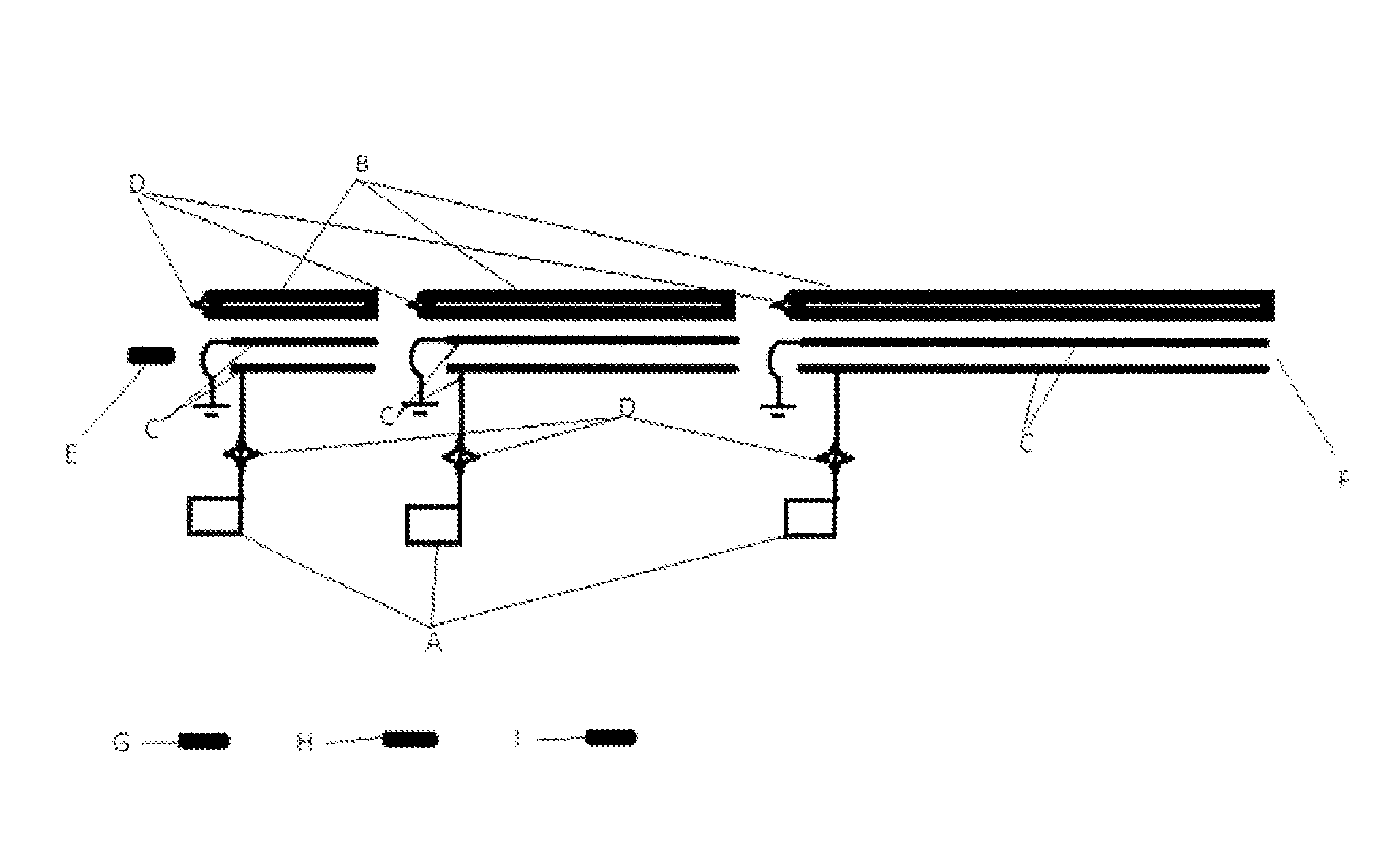
[0025]The invention is comprised of a transmission line structure of inductive and capacitive elements [FIG. 3] external to but in close proximity to the associated railgun drive rails [FIG. 2]. By adjustment of these local capacitive and inductive elements, the line phase velocity of a transmission line associated pulse or traveling wave structure is defined external to the said railgun drive rails, which provides for a continuously co-traveling with between drive rail armature, as such phase matched, induced and impressed magnetic field structure. Phase matching within the context of this discussion relates to the co propagation of the optimal location of a pulse or traveling wave structure, carried by a transmission line, with the time dependent location of an armature / projectile traveling between the drive rails of the associated close coupled rail element. Since the acceleration behavior of the armature / projectile within this structure is predictable and repeatable for a common projectile of specified mass and other relevant physical features, inclusive of repeatable railgun energization parameters, achievement of said phase matching is viable.
[0028]The forgoing eliminates the requirement of having to switch multiple individual coils sequentially along a given rail element. For each rail segment there are only two switching events associated with entry of armature to rail. Transmission line structure is switched such that the centroid of the induced co-traveling magnetic B field matches armature location on its entry to rail element concerned. Once armature has progressed sufficiently into the rail element, such that decaying spatial edge of co-traveling spatially limited B field structure is adequately opposing the back emf attributable to armature forward motion and its B field interaction, then rail element discharge current itself is turned on [FIG. 1, A].

Problems solved by technology

If the rails were superconducting, the preceding would be avoidable, but there would be technical issues in regards preventing solid ice accumulation on rail surfaces.
Aside from the running surface difficulty presented by on rail ice, moisture accretion within a high voltage environment is less than desirable.
Short of effective sustained dry gas purging or in vacuum applications, this would be unavoidable.
This results in rail erosion much as a welding arc would.
Radiation from intense arcing can produce plasma ahead of the armature, which becomes a self limiting problem in that induced plasma serves to oppose armature acceleration as it represents a local, higher density gas component.
Radiation from intense arcing and typically associated with plasma formation can produce / induce secondary plasma emission at some other location on the rail; this can close as a switch (commutate) resulting in a secondary arc and power leakage.
This is an additional complication and has the potential to ‘freeze’ metal onto the rail with each event, thus affecting subsequent launch attempts.
In the simple, basic level, two rail configuration plus armature, given that the full drive current is channeled through the two parallel rails for the length of the barrel (acceleration region), it is then a basic fact that, as armature moves from the entrance to the end of rail, the circuital self-inductance increases commensurately, which complicates the issue of efficient power delivery to the armature.
There are also the issues of energy storage in the augmenting system, losses and energy recovery at the very least.
As indicated, performance / efficiency and lifetime issues would be critical to any meaningful civilian application as distinct from military use.
However a more detailed evaluation of this concept shows that very high voltages could be needed to power the coils, so the concept may be unattractive for short barrels and high velocity applications.
There are a number of deficiencies apparent with this approach.
This as alluded to in the statement that, high velocities may be unattractive with this concept.
In addition, turning off the preceding coil precisely in sync with the coil turned on is just as significant an issue if one wishes to avoid any growth in system back electromotive force (by convention, emf) or odd induced transients courtesy of flux accretion in the volume defined by a common rail segment and armature.
The extension of this technology to the muzzle velocities (>7500 m / s) and energies (>10GJ) needed for direct launch of payloads into orbit is very challenging, but may not be impossible.
A railgun system concept is described here and technology development issues are identified.
In other words, the system is in fact a series array of simple augmented railguns, in which case the local module is subject to the back emf problems associated with the local externally applied / augmented field armature interaction, as the turn off of the preceding module element's augmenting fields does not counterpoint the turn on of the augmenting fields in any other separate module.
It is further apparent that within this technical approach, the externally applied magnetic field will in general not be optimal within the duration of the armature acceleration event.
The latter may not be significant for small bore, moderate velocity systems, but will be significant to prohibitive at larger bore and higher velocities and thus presents a scalability issue.
Finally, if the objective was to accelerate a projectile to +20 km / s the switching and timing requirements and the associated voltages and currents of a sequenced individual coil series array would become severe.
This is no different to the problem presented by the coil switching issue in pure induction accelerators such as coil guns, where the voltage required increases with velocity and thus high voltage commutation of multiple coils in axial series represents the technological limit to achievable launch velocity.

Method used


Image

  • Traveling wave augmented railgun
  • Traveling wave augmented railgun
  • Traveling wave augmented railgun

Examples


Embodiment Construction

[0043]The best mode contemplated by the inventor of the rail gun with principle rail energization and fielding derived from a co-traveling energy pulse is comprised of at the basic system unit level, of a rail element plus associated transmission line structure and related power supplies and switching assemblies. That is a rail segment.

[0044]The global system is typically made up of a sequenced series of rail segments. The number of rail segments in a sequence is determined by requirements such as deliverable exit velocity, tolerable acceleration, aero-shell design mass and related aperture requirement and costing.

[0045]Each rail segment is comprised of a rail element plus matched power supply. Close-coupled to rail element of rail segment is a transmission line structure designed to provide for a spatially limited, relative to rail element length, co-traveling with armature current, and thus magnetic field, pulse [FIG. 1, A, B, C, D, E]. This is accomplished by appropriate design m...


PUM


Abstract

A railgun launcher with principle rail energization and fielding derived from a co-traveling energy pulse associated with a close-coupled parallel transmission line structure. Enhanced system efficiency, plus amelioration of simple railgun negative features, is enabled via the induction hybrid railgun methodology proposed.

Description

BACKGROUND OF INVENTION[0001]1. Field of Invention[0002]The present invention relates to the field of electrically energized rail launchers, more specifically, an electromagnetic launcher / induction hybrid railgun with principle rail energization and fielding derived from a co-traveling energy pulse associated with a close-coupled parallel transmission line structure.[0003]2. Description of Prior Art[0004]There is an extensive history in regards these devices. At a very basic level, they are a linear electrical motor. Two conductors with an armature, free to move, providing the conduction connection between the rails. The approach is typically alternatively identified as a railgun or electromagnetic launcher. In order to drive an object of any reasonable mass to some useful velocity, typically very high currents in the multi mega-amp (MA) range are required in such a device. This requirement has specific practical problems that are inextricably associated with it and, to enumerate a ...

Claims


Application Information

Patent Timeline
Patent Type & Authority Patents(United States)
IPC IPC(8): F41B6/00
CPCF41B6/003B64G5/00
Inventor CAMPBELL, ROBERT, NEIL
Owner CAMPBELL ROBERT NEIL
Why Eureka
Try Eureka