Microwave one-to-N power divider

A technology of power divider and divider, which is applied in the direction of waveguide devices, electrical components, connection devices, etc., can solve the problems of no ground terminal, complex design of classic circuits, and increased circuit size

Active Publication Date: 2016-02-10
AIR FORCE UNIV PLA
View PDF4 Cites 3 Cited by
  • Summary
  • Abstract
  • Description
  • Claims
  • Application Information

AI Technical Summary

Problems solved by technology

[0003] The limitations of the current state of the art are: the grounding resistance of the Wilkinson power divider needs to be connected across two wires, and there is no grounding terminal, so it cannot be applied to high-power occasions; on the other hand, its broadband design must be multi-level connected, resulting in an increase in circuit size
Classic circuit design complex

Method used


Image

  • Microwave one-to-N power divider
  • Microwave one-to-N power divider
  • Microwave one-to-N power divider

Examples


Embodiment Construction

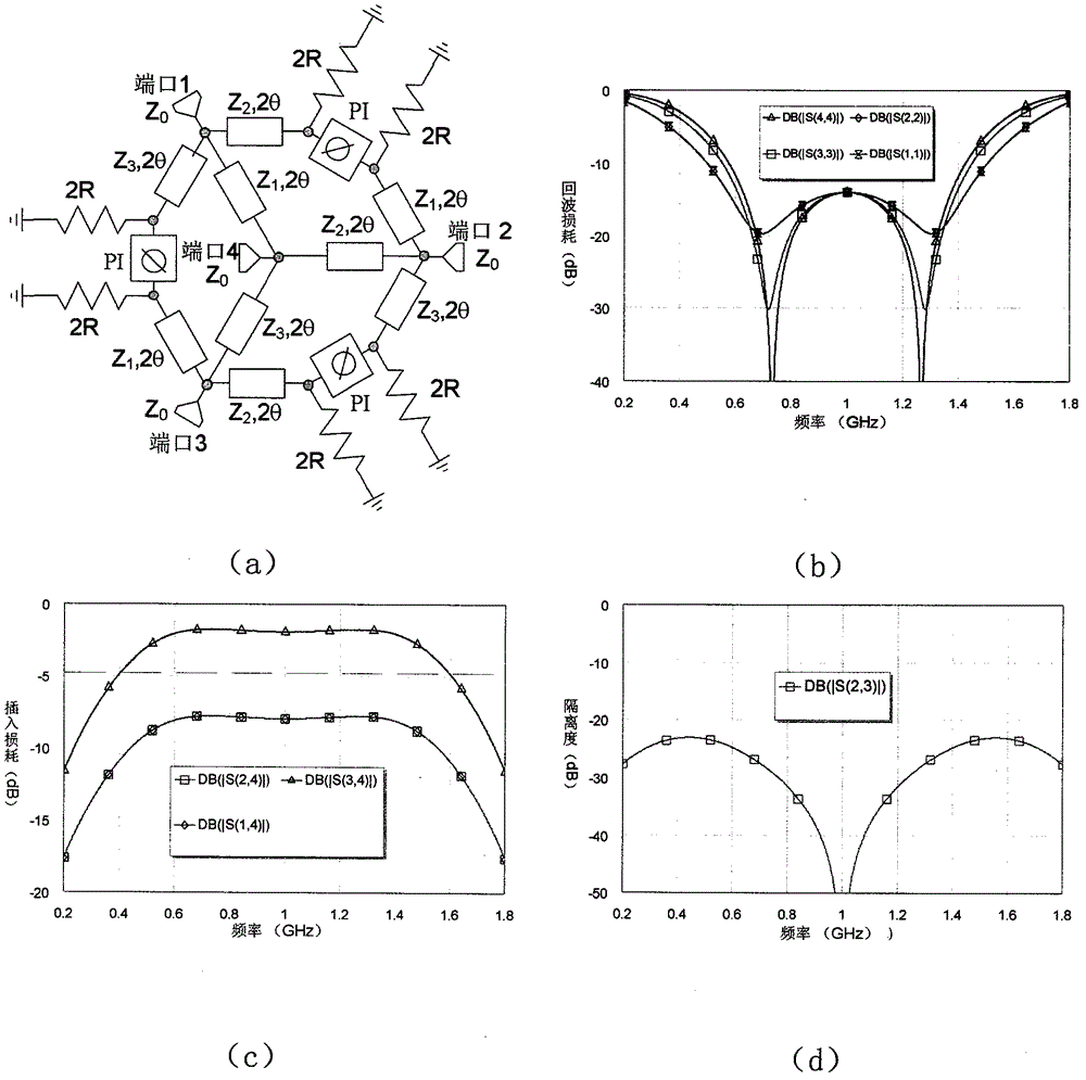
[0033] The one-to-N power divider with arbitrary power division ratio of broadband high-power in-phase (anti-phase) microwave proposed by the present invention will be further described in conjunction with the accompanying drawings.

[0034] like figure 1 Shown is the ideal inverter based on the present invention, with The structure of a broadband high-power microwave arbitrary power divider with a grounding resistor and output in the same phase is a split-N power divider, wherein the resistance value of each grounding resistor is 2R. Grounding resistance grounding, suitable for high-power occasions. Set the characteristic impedance as Z 0 The sum port N+1 is divided into electrical lengths of 2θ (2θ=90 degrees), and the characteristic impedance is Z 1 ,Z 2 ......Z N The parallel N branch line transmission lines (denoted as Z in the figure 1 , 2θ, Z 2 , 2θ...Z N, 2θ), the input terminals of the N branch transmission lines are all connected to port N+1, and the output ...


PUM


Abstract

The invention provides a microwave one-to-N power divider which is based on an ideal phase inverter, and is provided with P grounding resistors and N output ends. A sum port N+1 with the characteristic impedance being Z0 is divided into N parallel branch transmission lines Z1, 2theta, Z2, 2theta,..., ZN, 2theta, wherein the characteristic impedances of the N parallel transmission lines are respectively Z1, Z2,...,ZN., and 2theta is 90 degrees. The input ends of the N parallel branch transmission lines are connected with the sum port N+1, and the output ends of the N parallel branch transmission lines respectively serve as N power distribution output ports. Each two N power distribution output ports are connected with each other through two transmission lines with the length 2theta, wherein the characteristic impedances of the two transmission lines are the characteristic impedances of branch circuits where the corresponding ports belong, and the transmission line connected with the port K must not be the transmission line where the port K belongs (K is not less than zero and not greater than N). Moreover, an isolation network is connected in series between the two transmission lines. The power divider can provide all-in-phase and partial-inverted-phase and partial-inverted-phase power output. Compared with the prior art, the power divider greatly reduces the number of isolation resistors, and is especially suitable for broad-band large-power application occasions.

Description

technical field [0001] The invention relates to a microwave-divided-N power divider, in particular to an ideal inverter based one or A wideband high-power in-phase (inverted) microwave arbitrary power divider with a grounding resistance and two forms of in-phase output or inverting output. Background technique [0002] Microwave power divider is one of the basic components in microwave circuits and systems, and is widely used in circuits and systems such as microwave power amplification, microwave frequency mixing, and antenna array feed. The classic microwave power divider is divided into two types: Wilkinson power divider and Gysel power divider, both of which can realize the power distribution of one-point-N in-phase arbitrary power distribution ratio. Inverting power distribution is widely used in circuits such as differential antenna feed and push-pull amplifiers, and the corresponding power distribution circuit needs special design to meet the requirements of inver...

Claims


Application Information

Patent Timeline
Patent Type & Authority Applications(China)
IPC IPC(8): H01P5/12
Inventor 张旭春谢军伟王同洋
Owner AIR FORCE UNIV PLA
Why Eureka
Try Eureka