Current transfer logic

一种逻辑电路、电流的技术,应用在逻辑信号领域,能够解决电压偏移、检测电路操作不利影响等问题

Inactive Publication Date: 2007-02-28
FAIRCHILD SEMICON CORP
View PDF1 Cites 4 Cited by
  • Summary
  • Abstract
  • Description
  • Claims
  • Application Information

AI Technical Summary

Problems solved by technology

If there is an imbalance, the voltage across Rt may shift which can adversely affect the operation of the detection circuit

Method used


Image

  • Current transfer logic
  • Current transfer logic
  • Current transfer logic

Examples


Embodiment Construction

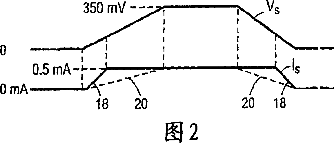
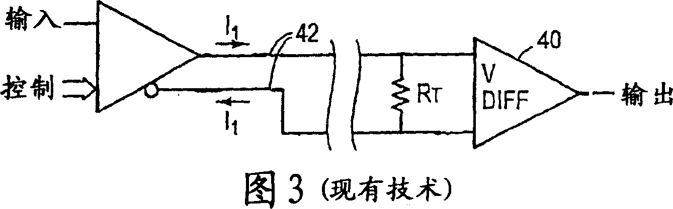
[0025] Figure 4A shows a diagram of a preferred embodiment of the invention. The input signal Vin controls and selects the output current signals Ia and Ib that are driven into the transmission lines 50 and 52 . In one logic state, Ia is a positive current output into the first transmission line 50 and Ib is a negative current input from the second transmission line 52 . In the opposite logic state, Ia is a negative current entering from the first transmission line 50 and Ib is a positive current entering the second transmission line 52 . In another preferred embodiment, it is also possible that no current is driven into any of the transmission lines.

[0026] If each transmission line has a characteristic impedance of 50 ohms, an Rt of 100 ohms is placed between the ends of the signal wires and used to terminate the two transmission lines. It is important that Ia and Ib are not equal to each other so that there is a return current through the shield. Also, since Rt is conn...


PUM


Abstract

The invention discloses a current mode transmission logic system for driving a transmission line. In one embodiment, the twisted pair transmission line is terminated at its transmission line characteristic impedance. The signal is formed by two unequal currents, preferably of different polarity and magnitude, driven down the two transmission lines. The unequal currents are selectively switched between the two transmission lines to generate differential current-driven logic signals of unequal current magnitudes. The unequal currents are received via diode-connected MOS transistors and shunted from the end of each transmission line. MOS transistors are biased to present a low impedance, but this impedance is higher than the termination resistance. The current is amplified and converted to usable CMOS voltage levels. In another embodiment, the twisted pair is replaced by two parallel transmission lines terminated in a resistor equal to the sum of the characteristic impedances of each transmission line. The terminating resistors are connected between the end signal-carrying conductors of each transmission line. The shield or return path of each transmission line is connected at the end of the transmission line to the nearest (drive end).

Description

technical field [0001] This invention relates to sending logic signals over terminated transmission lines, and more particularly to sending differential signals over transmission lines. Background technique [0002] The technique of sending logic (and analog) signals over transmission lines while maintaining fidelity by utilizing impedance matching of such signals has attracted attention in many technical fields, especially in communication and computer systems, over the years. This area has become increasingly important as system speeds increase and power consumption requirements decrease. [0003] In logic and computer systems, transmission line drivers are typically activated by sending unipolar logic (voltage) signals on matched transmission lines. Types of transmission lines used in the above systems include, but are not limited to, single and paired conductors, twisted pairs, shielded twisted pairs, flat cables, flat cables with grounded shields, and coaxial cables. ...

Claims


Application Information

Patent Timeline
Patent Type & Authority Applications(China)
IPC IPC(8): H04L25/02
CPCH04L25/0272H04L25/0278H04L25/0282H04L25/0294H04L25/02H04B3/54H04B3/00
Inventor 普拉瓦斯·普雷德汉周建宏
Owner FAIRCHILD SEMICON CORP
Why Eureka
Try Eureka