
Bleed area adjustment technique for use in printing multiple articles of manufacture

a technology of bleed area and adjustment technique, which is applied in the field of simultaneous printing, can solve the problems of misplaced image on the article, transfer of ink or ink dust to subsequent items, and difficulty in precisely positioning the articles of manufacture, so as to reduce the amount of ink used, reduce and adjust the width of the bleed area

Active Publication Date: 2014-03-18
CIMPRESS SCHWEIZ
View PDF5 Cites 4 Cited by
  • Summary
  • Abstract
  • Description
  • Claims
  • Application Information

AI Technical Summary

Benefits of technology

[0010]It is an advantage of the invention that an ink bleed adjustment parameter allows adjustment of a default ink bleed width. This allows an operator or automatic process to monitor actual print characteristics and actual need for the full bleed area, and to adjust the width of the bleed area to reduce its width when the full bleed is not needed. This reduces the amount of ink utilized and therefore reduces the amount of printing costs. It also reduces the amount of ink applied to the carrier (and not to the actual articles of manufacture), thereby reducing the amount of cleanup required.

Problems solved by technology

However, oftentimes the article of manufacture to be printed on is much smaller than the print area that the printer is capable of printing, and thus much of the total print time is spent in loading the article onto the printer pallet and subsequently removing it from the pallet after the printing is complete.
One difficulty in simultaneously printing multiple articles of manufacture that fit within the print area that the printer is capable of printing is the complexity involved in precisely positioning the articles of manufacture such that the respective image printed on each of the respective articles of manufacture is accurately aligned on the articles of manufacture in the precise position on the article of manufacture that the image is supposed to appear.
Any misalignment of an article of manufacture on the printer pallet results in misplacement of the image on the article of manufacture, and can also result in the application of ink on areas of the article of manufacture and / or pallet where ink should not be.
Residual ink on the pallet due to ink overspray from misalignment of the articles of manufacture can result in the transfer of ink or ink dust to subsequent items placed on the pallet.
Another reason that multiple items are typically not simultaneously printed is the complexity of instructing the printer exactly where to print each image on each article of manufacture on the pallet.
Building the combination image file, however, is not an easy task, as it involves both knowledge of the precise position of each article of manufacture on the pallet and the precise position of the printable area of each article of manufacture to be loaded onto the pallet, and knowledge of the mapping of pixels in the combination image file to the physical points on the pallet.
Yet a further complication in having the printer print multiple articles of manufacture at the same time is that even if the printer can be instructed, via the single image file that it receives, to print image content only on certain areas of the articles of manufacture on the pallet, the printing process generally results in at least some ink overspray (i.e., ink sprayed or splattered beyond the intended area of the printed image), which, depending on the placement of the image on the article of manufacture, can end up being applied to the pallet itself.
This unintentionally transferred ink or ink dust can render flaws on subsequent articles of manufacture printed on the pallet.

Method used


Image

  • Bleed area adjustment technique for use in printing multiple articles of manufacture
  • Bleed area adjustment technique for use in printing multiple articles of manufacture
  • Bleed area adjustment technique for use in printing multiple articles of manufacture

Examples


Embodiment Construction

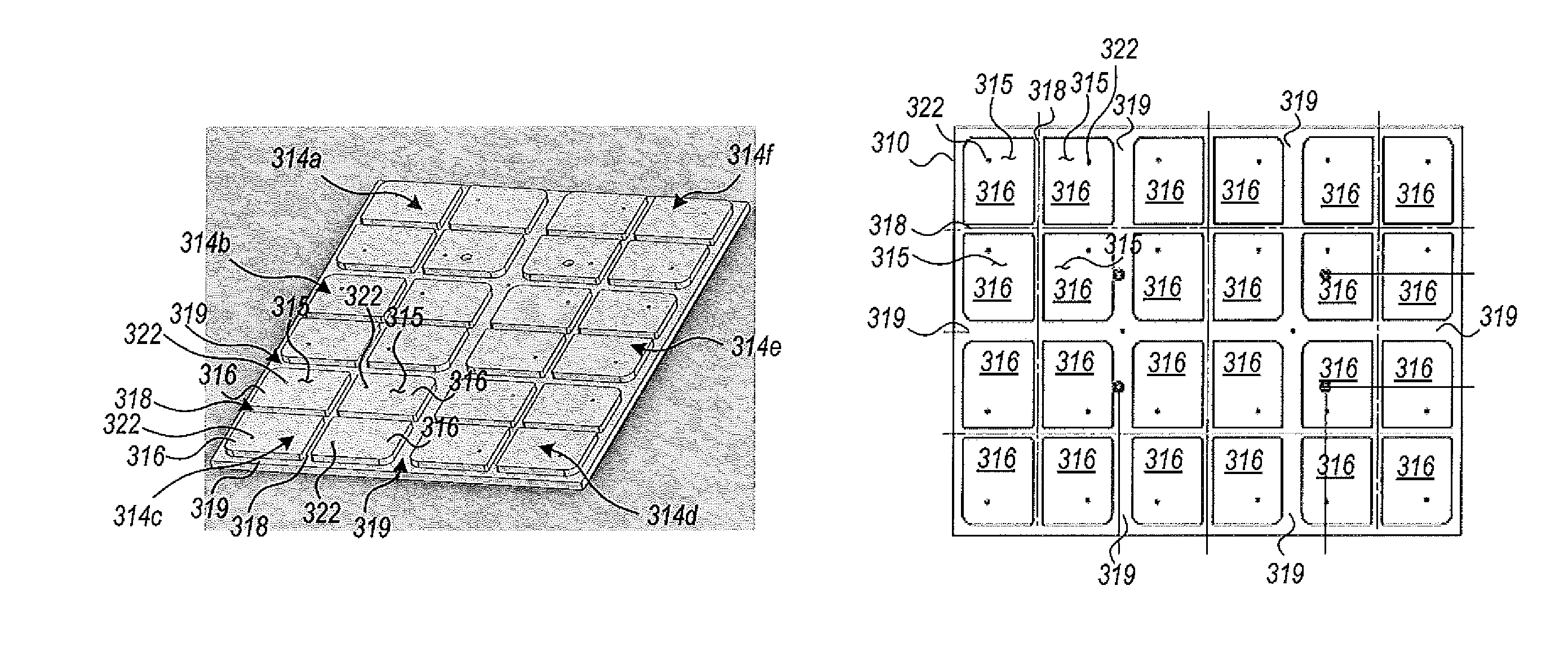
[0049]It will be understood that while the discussion herein describes an embodiment of the invention in the field of preparation of customized printed mouse pads, the invention is not so limited and is relevant to preparation and simultaneous printing of multiple articles of manufacture, where the articles of manufacture may be any object capable of being printed on by a printer, and in particular a printer pallet supporting multiple separate articles of manufacture, which may include a removable tray and a positioner for assisting in the precise placement of articles onto the pallet.

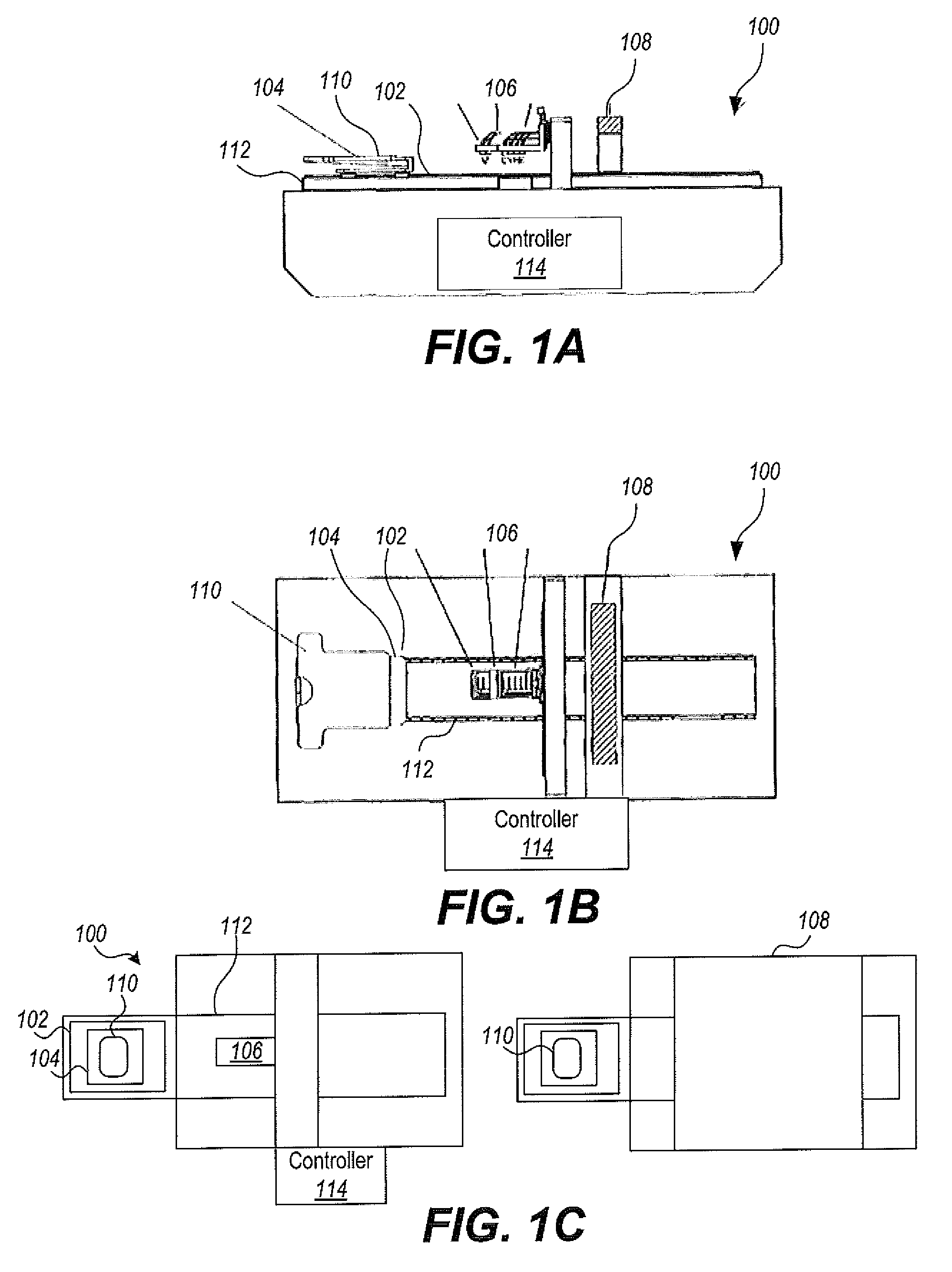
[0050]FIGS. 1A and 1B illustrate a digital image printer 100 for printing digital images directly onto an article of manufacture such as a mouse pad. The printer 100 includes a printing table 102 having a pallet 104 mounted thereon for holding an article of manufacture 110. The printer 100 also includes an array of inkjet print heads 106 and a drying unit 108. The printing table 102 is mounted on a con...


PUM


Abstract

Techniques for creating an individual image sized to a desired print area plus a desired amount of bleed area to thereby reduce an amount of ink applied outside a desired print area are presented. In an embodiment, each of the desired print area dimensions, a default ink bleed width, and an ink bleed adjustment setting are obtained. The individual image comprises an image container sized to a desired print area plus a desired amount of bleed area. Each of the respective dimensions of the image container of the individual image is set to the corresponding respective dimension of the desired print area plus the default ink bleed width. A base image providing image content for the image container is sized to the dimensions of the image container if dimensions of the base image do not already equal the dimensions of the image container. If an adjustment to the bleed area is required, an adjustment setting indicative of a desired width of the ink bleed is obtained, and a white frame is inserted around the inside perimeter of the individual image, the white frame having a width equal to the difference between the default ink bleed width and the desired width of the ink bleed.

Description

FIELD OF THE INVENTION[0001]This invention relates to simultaneous printing of multiple images onto multiple articles of manufacture, and more particularly to a novel technique for combining individual images to be printed onto respective articles of manufacture into a single print file for simultaneous printing onto the multiple articles of manufacture by a printer.BACKGROUND OF THE INVENTION[0002]Various methods of direct printing of images or graphic designs onto textiles and various other non-paper substrates exist. In the industrial setting, an article on which an image is to be printed, for example an item of apparel such as a t-shirt, is typically loaded and secured onto a pallet such that the print surface of the article is secured in place. Typical industrial printers are designed for processing and printing only a single image file at a time. Consequently, prior art pallets have been designed for printing on a single substrate (e.g., a single sheet of paper, foam, fabric, ...

Claims


Application Information

Patent Timeline
Patent Type & Authority Patents(United States)
IPC IPC(8): B41J2/205G06F3/12G06K15/02
CPCH04N1/387
Inventor HYMAN, JACOB, A.
Owner CIMPRESS SCHWEIZ
Learn More