
System and method for controlling a furnace

a technology of system and method, applied in the direction of combustion control, combustion types, domestic cooling apparatus, etc., can solve the problems of affecting the operation of the combustion system, the inability of the combustion system to dependably be factory set to a particular speed or flow rate, and the inability to control the flow rate of the furna

Active Publication Date: 2014-03-18
TRANE INT INC
View PDF25 Cites 12 Cited by
  • Summary
  • Abstract
  • Description
  • Claims
  • Application Information

AI Technical Summary

Benefits of technology

The patent text describes a method and apparatus for controlling a modulating gas furnace. The method involves monitoring the pressure in the furnace using multiple pressure switches and a low pressure limit switch. The furnace can operate in different modes based on the pressure settings of the switches. The technical effects of this patent text include improved control of the modulating gas furnace and improved efficiency in response to varying demands for output.

Problems solved by technology

It is known that draft inducers cannot dependably be factory set to a particular speed or flowrate in a manner that accommodates for the wide variation of installation furnace configurations and transient pressure fluctuations that may be present amongst different installation locations.
For example, in some gas furnaces, a combustion system may be halted from operation when one or more of a temperature limit sensor, a pressure switch, and a gas valve relay are in states inconsistent with safe operation.
Specifically, if a temperature limit sensor reports that a temperature is too high the combustion system may be turned off.
Similarly, if a pressure switch that ensures a safe amount of exhaust flow reports that exhaust flow is not sufficient, the combustion system may be turned off.
Further, if a gas valve relay is inappropriately in an open state, the combustion system may be turned off.

Method used


Image

  • System and method for controlling a furnace
  • System and method for controlling a furnace
  • System and method for controlling a furnace

Examples


Embodiment Construction

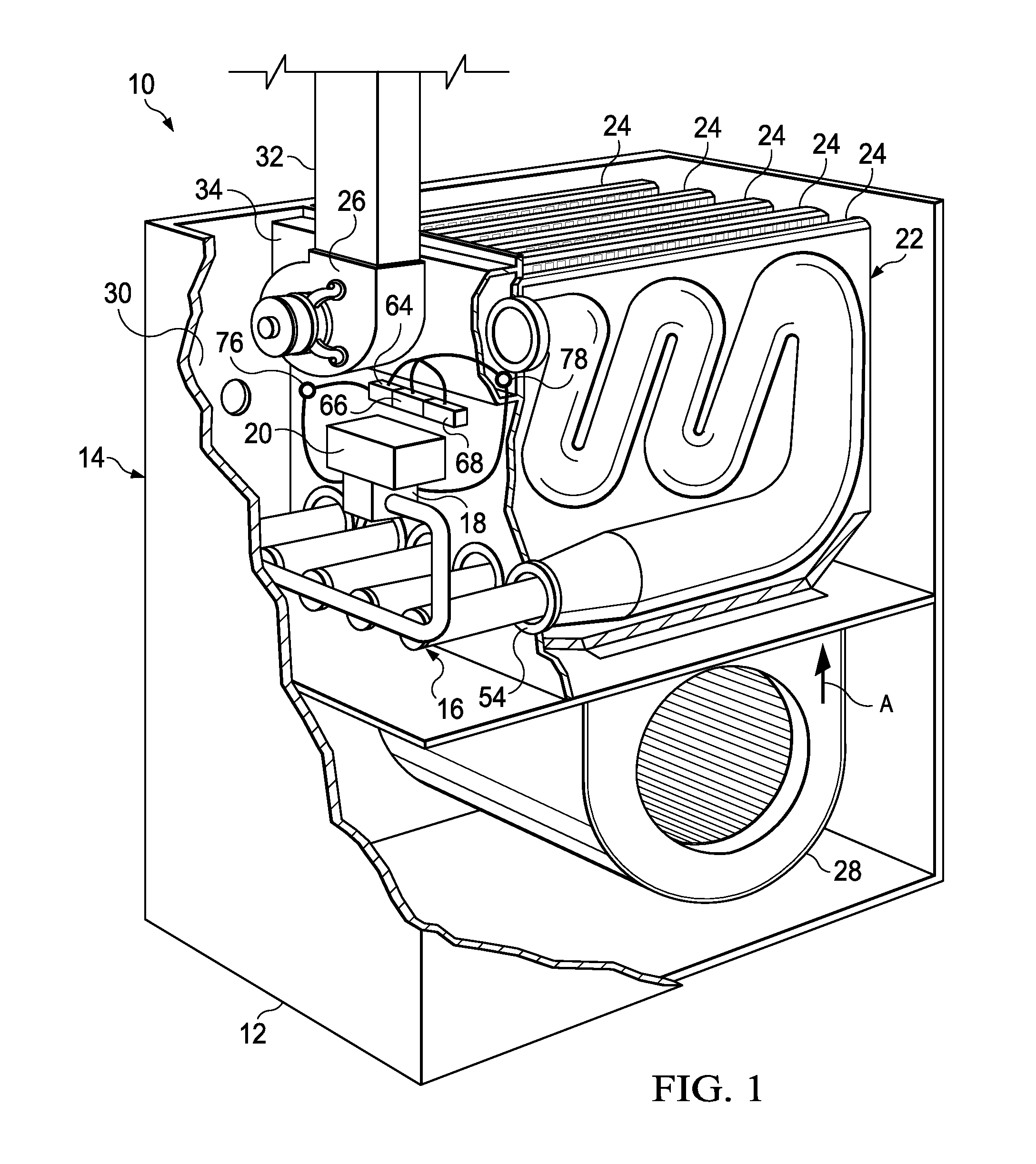
[0020]Some gas furnaces are configured as variable output capacity devices (also referred to as “modulating furnaces”). Due to the inherent difference in some modulating gas furnaces from other types of gas furnaces, i.e. mechanically ensuring that the provision of fuel gas is in proportion to exhaust and / or oxygen flow, current safety methods may unnecessarily contribute to interruptions in operation of a modulating gas furnace and with no added safety benefit. More specifically, and as further described below, because a modulating gas valve may be pneumatically or otherwise linked to provide fuel gas in response to an actual pressure differential, there is no risk that extraneous fuel gas will be emitted out of proportion to the actual oxygen and exhaust flow provided. Accordingly, the present disclosure provides systems and methods for safely controlling a modulating gas furnace with reduced interruptions in operation while also providing systems and methods for ensuring operatio...


PUM


Abstract

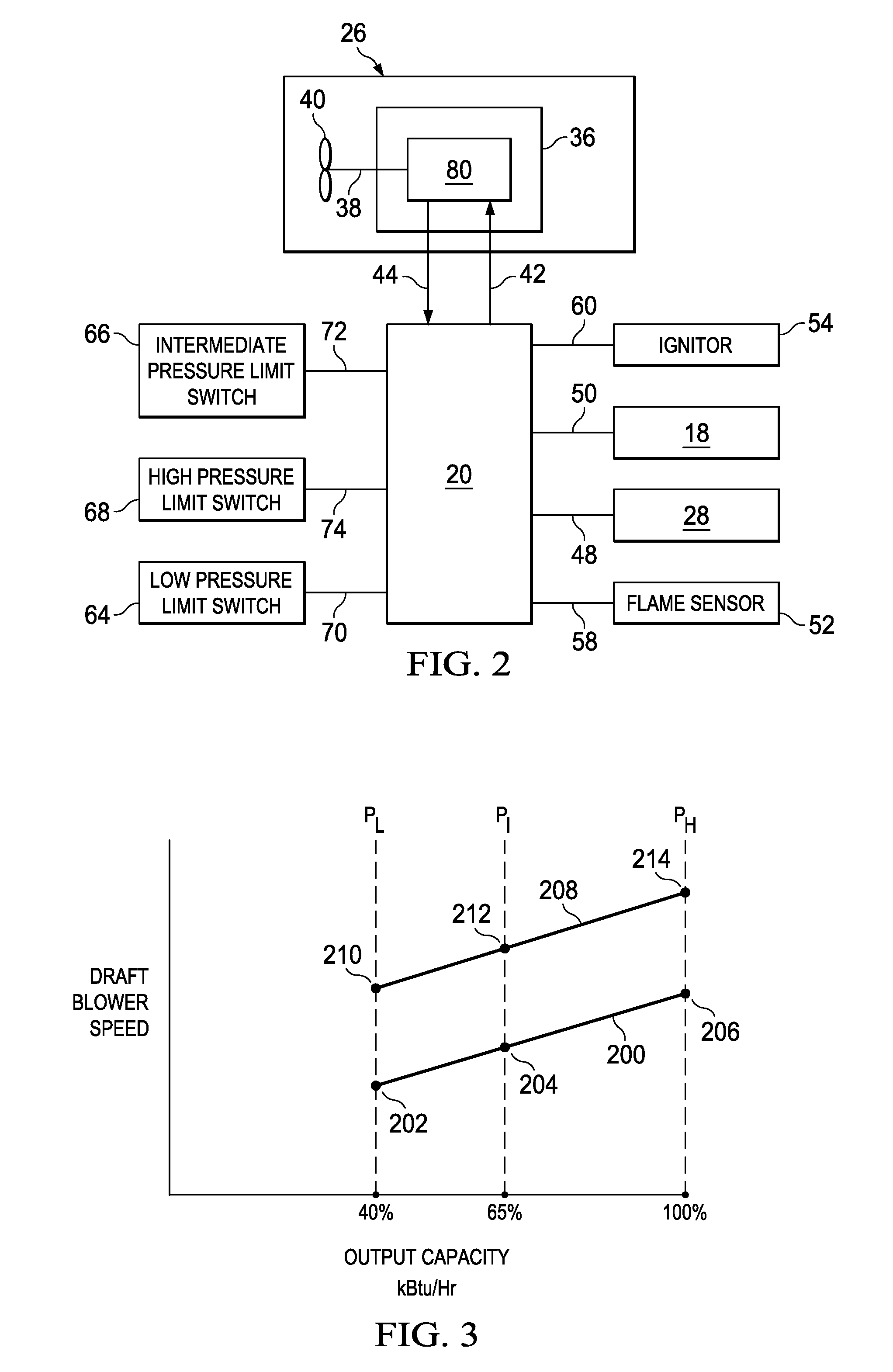
Controlling a modulating gas furnace by monitoring a differential pressure associated with the modulating gas furnace using a low pressure limit switch configured to actuate at a first pressure, an intermediate pressure limit switch configured to actuate at a second pressure, and a high pressure limit switch configured to actuate at a third pressure, the second pressure being between the first and third pressure, selectively operating the modulating gas furnace in one of a cycling mode, a modulating mode in a lower range, and a modulating mode in an upper range, the modulating mode in the lower range being associated with an output capacity range between the output capacity ranges of the cycling mode and the modulating mode in the upper range, and selectively operating the furnace in response to at least one of the low pressure limit switch, the intermediate pressure limit switch, and the high pressure limit switch.

Description

CROSS-REFERENCE TO RELATED APPLICATIONS[0001]Not applicable.STATEMENT REGARDING FEDERALLY SPONSORED RESEARCH OR DEVELOPMENT[0002]Not applicable.REFERENCE TO A MICROFICHE APPENDIX[0003]Not applicable.BACKGROUND[0004]Heating, ventilation, and air conditioning systems (HVAC systems) sometimes incorporate gas furnaces for providing a heating effect to temperature controlled areas or comfort zones. Some gas furnaces comprise draft inducers that pull flue gases resulting from combustion through heat exchangers. It is known that draft inducers cannot dependably be factory set to a particular speed or flowrate in a manner that accommodates for the wide variation of installation furnace configurations and transient pressure fluctuations that may be present amongst different installation locations. For example, some gas furnaces may be installed with substantially different lengths of piping connected to an exhaust vent. Accordingly, it is known to provide a furnace with a variable speed draf...

Claims


Application Information

Patent Timeline
Patent Type & Authority Patents(United States)
IPC IPC(8): F24H9/20
CPCF23N2005/182F23N2033/08F23N2041/02F23N3/082F23N2037/10F23N5/184F23N2025/04F23N5/242F23N2027/02F23N1/002F24D19/1084F24H3/06F23N2227/02F23N2225/04F23N2237/10F23N2241/02F23N2233/08
Inventor HUGGHINS, GORDON, JEFFREY
Owner TRANE INT INC
Learn More