Bearing arrangement for a tension roller
a technology of tension roller and bearing, applied in the direction of elastic bearing, rigid support of bearing unit, transportation and packaging, etc., can solve the problem of covering as a noise source, and achieve the effect of reducing the formation of fretting corrosion, absorbing shock-like loads, and preventing micro movements
- Summary
- Abstract
- Description
- Claims
- Application Information
AI Technical Summary
Benefits of technology
Problems solved by technology
Method used
Image
Examples
Embodiment Construction
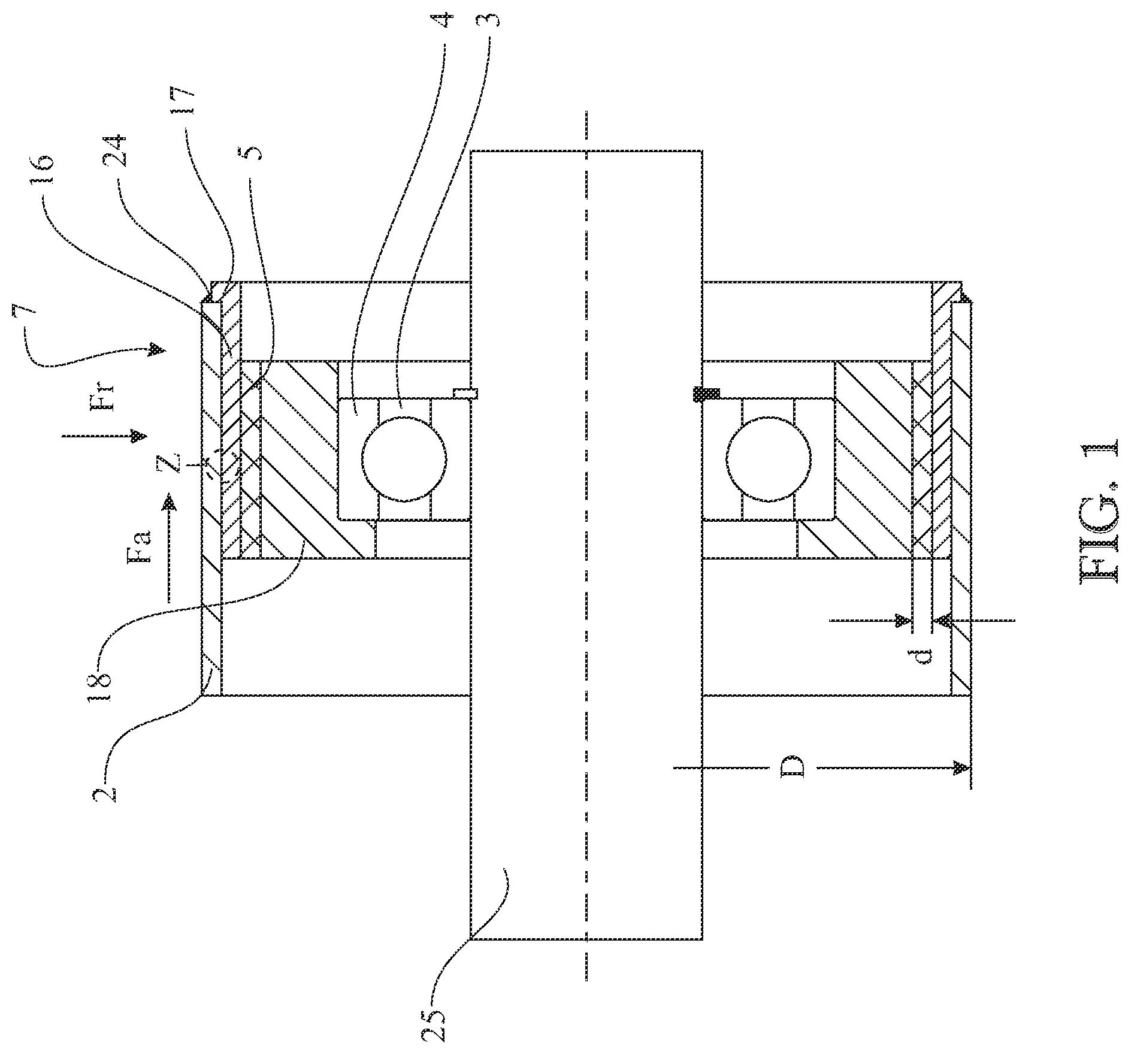
[0041]In FIG. 1 can be seen a bearing arrangement 1 which serves for supporting a carrying roller 2 of a conveyor device. A shaft 25, on which a grooved ball-bearing 3 is secured, is illustrated. The outer ring 4 of the grooved ball-bearing 3 carries a carrier body 18 having a one-sided rim which surrounds the outer ring 4 axially and forms an axial bearing surface for the latter.
[0042]The carrying roller 2 is designed as a hollow-cylindrical component, that is to say as a tube, a bearing arrangement 1, as can be seen in FIG. 1, being arranged in the two axial end regions. A sleeve-shaped body 16 is pressed into the inwardly directed surface of the carrying roller 2 and is seated with a press fit in the carrying roller 2. A damping layer 5 composed of elastomeric or rubber material is arranged between the sleeve-shaped body 16 and the carrier body 18 and in the present case is designed as a hollow-cylindrical layer. The elastomeric or rubber material may be connected directly to the...
PUM
 Abstract
Description
Claims
Application Information
 - R&D
- Intellectual Property
- Life Sciences
- Materials
- Tech Scout
- Unparalleled Data Quality
- Higher Quality Content
- 60% Fewer Hallucinations
Browse by: Latest US Patents, China's latest patents, Technical Efficacy Thesaurus, Application Domain, Technology Topic, Popular Technical Reports.
© 2025 PatSnap. All rights reserved.Legal|Privacy policy|Modern Slavery Act Transparency Statement|Sitemap|About US| Contact US: help@patsnap.com


