
Wheel drive system for aircraft with a fuel cell as energy source

a fuel cell and aircraft technology, applied in the direction of battery/fuel cell control arrangement, electrochemical generators, aircraft braking arrangements, etc., can solve the problem of only producing limited quantity of exhaust gases, and achieve the effect of reducing electric energy supply, and increasing electric energy supply

Inactive Publication Date: 2014-03-11
AIRBUS OPERATIONS GMBH
View PDF40 Cites 3 Cited by
  • Summary
  • Abstract
  • Description
  • Claims
  • Application Information

AI Technical Summary

Benefits of technology

[0007]It is the object of the invention to propose a wheel drive system for an aircraft including a corresponding energy source that makes it possible, in particular, to lower the exhaust gas and noise emissions. Additionally, it is an object of the invention consists to prevent prolonged operating times and increased maintenance costs for the main engines and the APU.

Problems solved by technology

A limited quantity of exhaust gases is only produced if the hydrogen is obtained from kerosene in the aircraft by means of a “reforming” process.

Method used


Image

  • Wheel drive system for aircraft with a fuel cell as energy source
  • Wheel drive system for aircraft with a fuel cell as energy source
  • Wheel drive system for aircraft with a fuel cell as energy source

Examples


Embodiment Construction

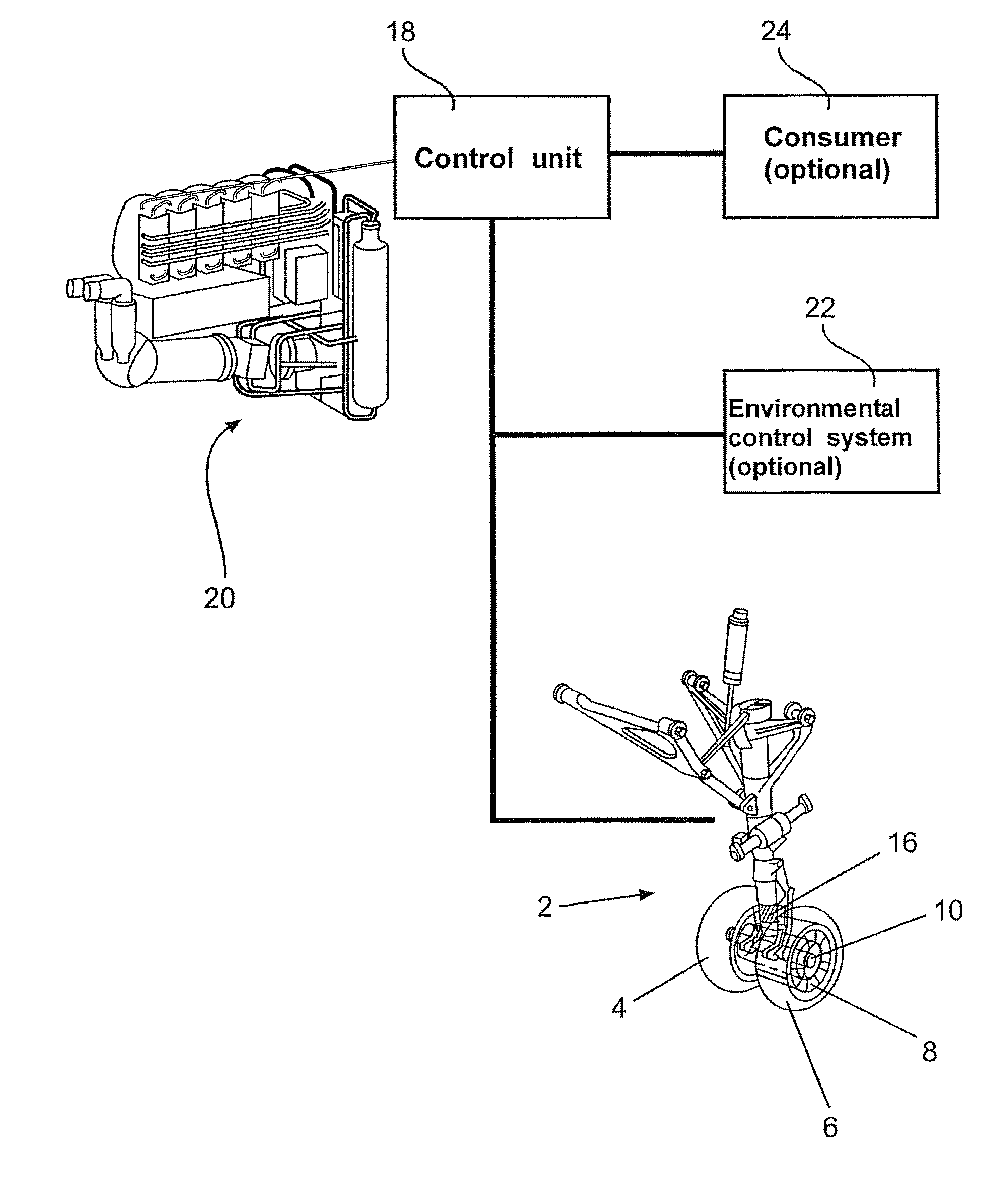
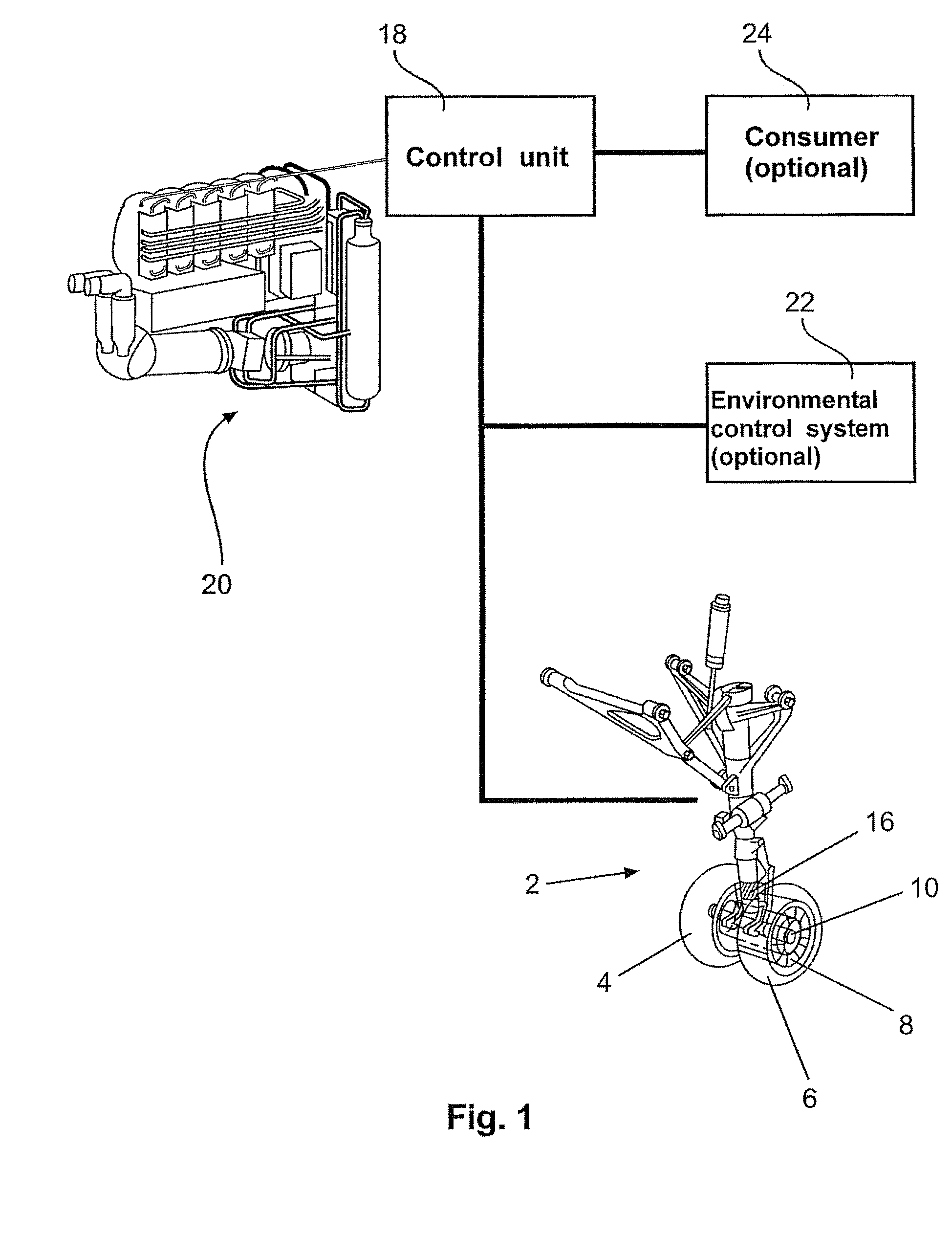
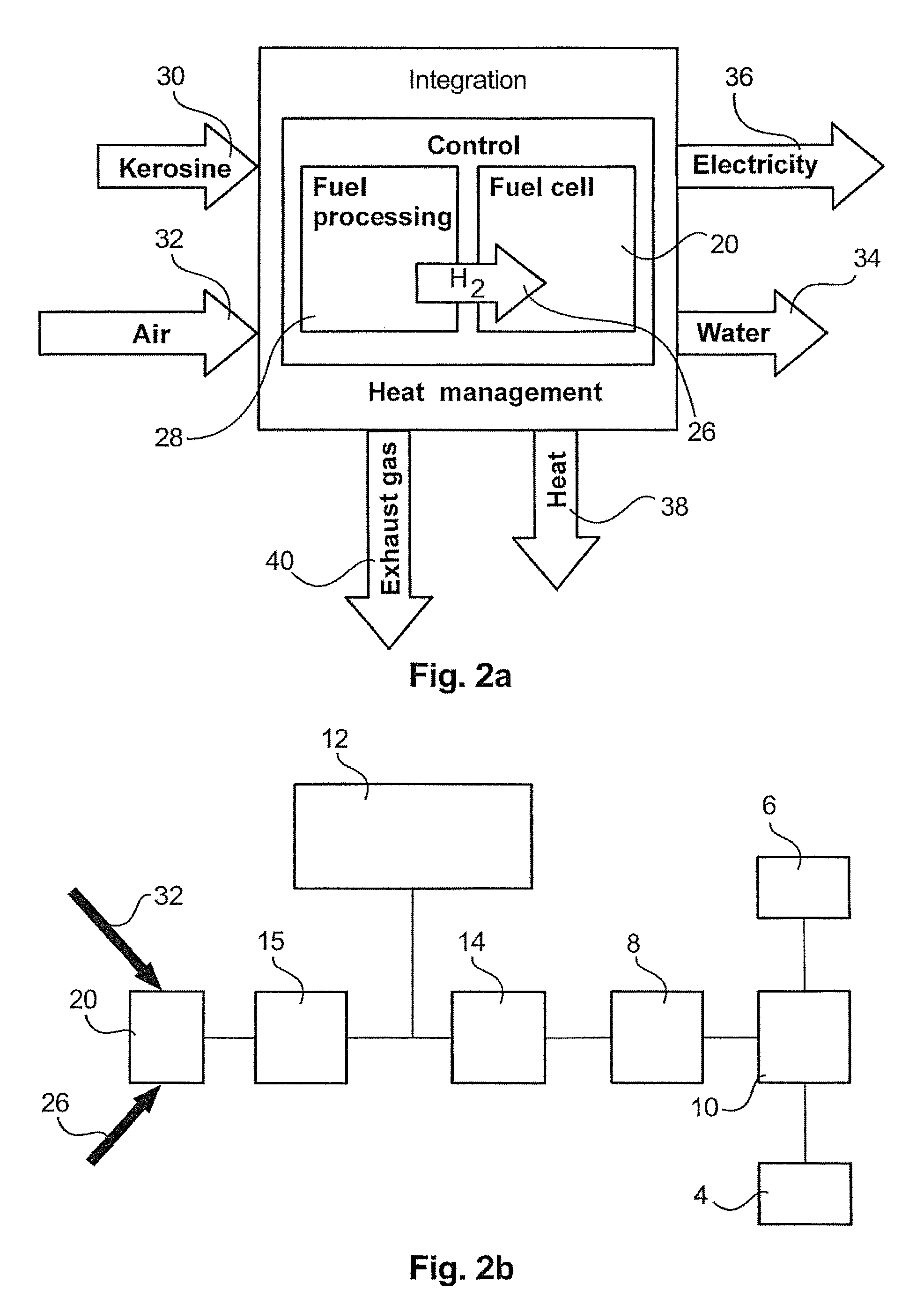
[0025]FIG. 1 shows an overview of one possible embodiment of the wheel drive system according to the invention. In addition to the usual assemblies such as wheels 4 and 6, tires, shock absorbers, latching mechanism, retracting mechanism, flaps, brakes and emergency lowering springs, the landing gear 2 also comprises the following assemblies: an electric motor 8, a gear drive 10 and control and measuring electronics / sensor 16. The electric motor 8 is coupled to the wheels 4 and 6 via a gear drive 10. A torque sensor 16 is used for determining the torque generated or absorbed by the motor 8. The determined torque value can be used, for example, for optimizing the braking process or an acceleration process and therefore the electric energy supply.

[0026]The electric motor 8 is connected to a control unit 18 that controls the supply of electric energy to the electric motor 8 and optionally to other consumers from and to a fuel cell 20. In the taxiing mode, the control unit 18 routes elec...


PUM

PropertyMeasurementUnit
torqueaaaaaaaaaa
electric energyaaaaaaaaaa
temperatureaaaaaaaaaa

Abstract

A wheel drive system for an aircraft that features at least one electric motor and at least one fuel cell as energy source for the electric motor, wherein the electric motor is coupleable to at least one wheel of at least one landing gear of the aircraft. The wheel drive system reduces the fuel consumption and lowers the emission of CO2 and pollutants—primarily carbon monoxide and unburned hydrocarbons. Persons, vehicles and other aircraft furthermore are not endangered by a jet blast while the aircraft is taxiing because the main engines do not have to be started until the take-off and landing strip is reached. The operation of the wheel drive system furthermore leads to a reduced noise pollution.

Description

CROSS-REFERENCE TO RELATED APPLICATIONS[0001]This application is a national phase entry under 35 U.S.C. §371 of International Application No. PCT / EP2009 / 058487, filed Jul. 6, 2009, published in German, which claims the benefit of the filing date of U.S. Provisional patent application No. 61 / 134,181, filed Jul. 7, 2008, and of German Patent Application No. 10 2008 031 933.3 filed Jul. 7, 2008, the entire disclosures of which are hereby incorporated herein by reference.TECHNICAL FIELD[0002]The invention relates to a wheel drive system for an aircraft, the use of a wheel drive system in an aircraft, as well as an aircraft with a wheel drive system and the use of a fuel cell as energy supply for a wheel drive system in an aircraft.BACKGROUND OF THE INVENTION[0003]The taxiing of aircraft between a parking position and a take-off and landing runway is usually realized with a tow tractor and / or with the thrust of the main engines of the aircraft. The tow tractor is required, in particular,...

Claims


Application Information

Patent Timeline
Patent Type & Authority Patents(United States)
IPC IPC(8): H01M8/04B64C25/42B64D41/00
CPCY02T90/34B64C25/405Y02T50/823B60L11/1894B60L11/1892B60K7/0007Y02T90/36B64D2041/005B60L2200/26B60L11/1881B60L58/30B60L58/33B60L58/34Y02T50/80Y02T90/40
Inventor ROTGER, THOMASHEINRICH, HANS-JURGENKURRE, JENS-DIETRICH
Owner AIRBUS OPERATIONS GMBH
Learn More