
Anhydrous ammonia fertilizer liquid and vapor separator

an ammonia fertilizer and liquid technology, applied in the direction of liquid fertiliser distribution, fertilizer equipment, agriculture, etc., can solve the problems of reducing the production efficiency of ammonia vapor, affecting the flow rate of ammonia vapor, and affecting the quality of ammonia vapor, so as to reduce the production of ammonia vapor, prevent excessive fertilizer application, and reduce the effect of ammonia temperatur

Inactive Publication Date: 2014-03-11
360 YIELD CENT
View PDF3 Cites 13 Cited by
  • Summary
  • Abstract
  • Description
  • Claims
  • Application Information

AI Technical Summary

Benefits of technology

The present invention is a method and apparatus for separating anhydrous ammonia from liquefied ammonia. The invention includes a basket filter in a tower preceding the vapor exhaust tower, which allows for longer operation and greater surface area to hold trash. The filter basket has a larger size than previously used commercial filters, which reduces the frequency of filter cleanings. The method and apparatus have been tested and have been found to improve operation and ease of use. The invention also includes a vapor discharge valve to control the amount of ammonia vapor released and a cooling system to prevent excessive fertilizer application. Overall, the invention provides better performance and more efficient operation for separating anhydrous ammonia.

Problems solved by technology

Anhydrous ammonia storage (nurse) tanks used on farms typically contain a significant amount of trash, particularly rust.
As the liquid stream passes through valves, fittings and a connecting hose to the applicator system it experiences a pressure loss due to friction in the hose.
In normal operation, rust and other trash from the storage tank fill the filter basket, eventually stopping flow to the tower.

Method used


Image

  • Anhydrous ammonia fertilizer liquid and vapor separator
  • Anhydrous ammonia fertilizer liquid and vapor separator
  • Anhydrous ammonia fertilizer liquid and vapor separator

Examples


Embodiment Construction

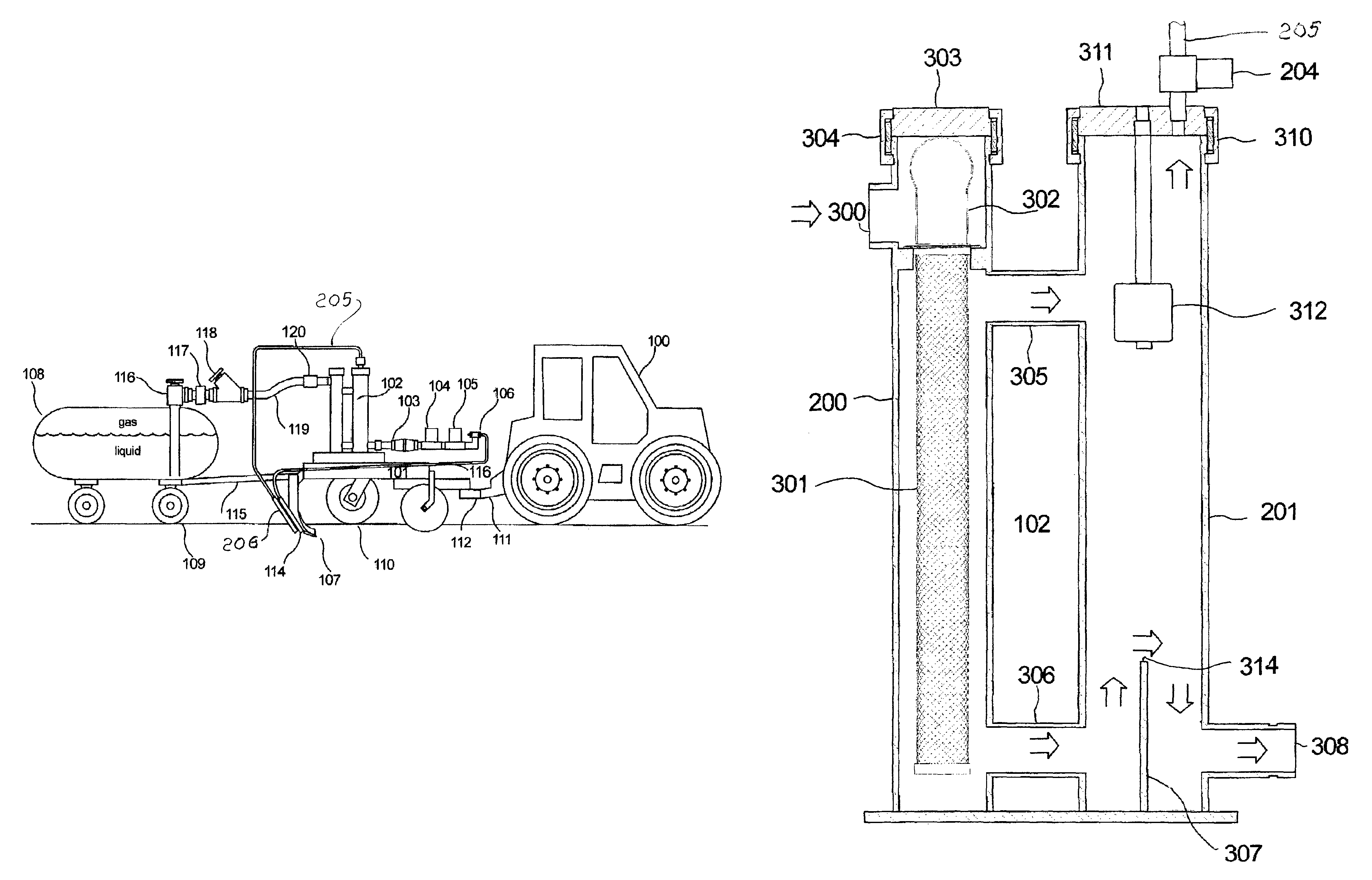
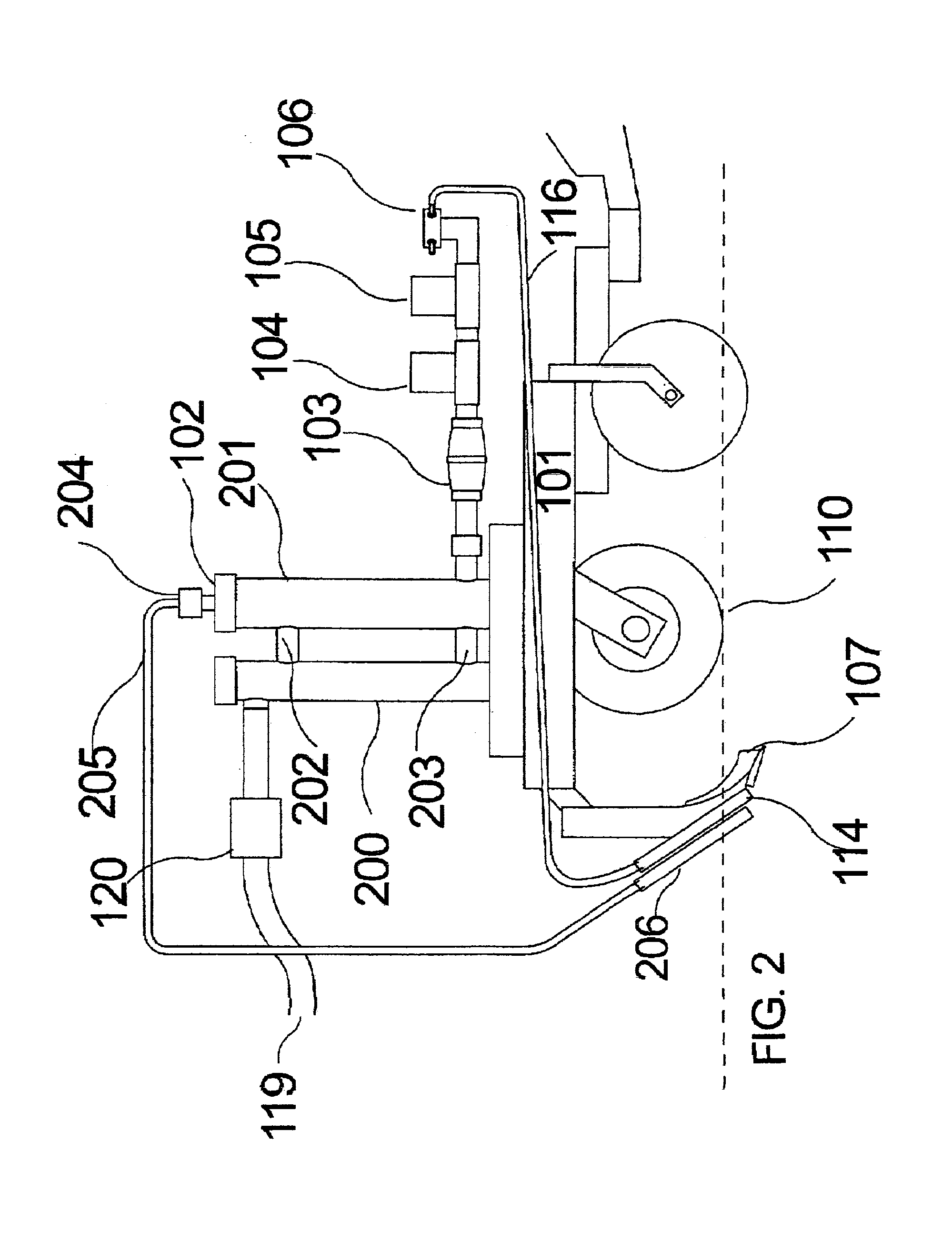
[0023]Referring first to FIG. 1, the apparatus of the present invention is shown being pulled behind a tow vehicle 100 which could be a tractor, truck, or the like. The apparatus includes a toolbar applicator frame 101 which supports a vapor exhaust assembly 102, a flow meter 103, an electrically operated flow control valve 104, an electrically operated shut off valve 105, a distribution manifold 106, a plurality of soil cutting knives 107, and a storage tank 108 supported on a plurality of wheels 109 and towed behind the toolbar applicator frame 101. The toolbar applicator frame 101 is itself supported on a plurality of wheels 110 and has a tongue 112 that is pivotally connected to a hitch 111 on the rear of the tow vehicle 100. In the preferred embodiment, the toolbar applicator frame 101 is a Progressive series 1300 anhydrous ammonia toolbar, manufactured by Progressive Farm Products, Inc. of Hudson, Ill. It is configured by Progressive for “strip till” ammonia application. Multi...


PUM


Abstract

The vapor exhaust assembly, for anhydrous ammonia, includes a closed filter tower and a closed exhaust tower with vertical tubes. The filter tower is connected to the vapor tower by a vapor upper pipe and a liquid lower pipe. A filter tube is mounted in the filter tower. Ammonia enters the filter tower above an open end of the filter. Ammonia vapor moves from the filter tower through the vapor upper pipe to a vapor chamber in the vapor tower. Liquid moves from the filter tower through the liquid pipe to the vapor tower. Liquid received in the vapor tower is moved upward by a dam. Vapor in the liquid moves upward to the vapor chamber. Liquid moves downward from the dam top to a liquid discharge exit. A vapor discharge valve in the top of the vapor tower is opened to discharge vapor and increase liquid in both towers.

Description

CROSS REFERENCE TO RELATED APPLICATION[0001]This application claims the benefit of the filing date of U.S. Provisional Application No. 61 / 355,523, titled IMPROVEMENTS TO AN ANHYDROUS AMMONIA FERTILIZER SEPARATOR FOR LIQUID AND VAPOR filed Jun. 16, 2010.TECHNICAL FIELD[0002]The present invention relates improvements to an apparatus and method for providing vapor free liquid to an anhydrous ammonia flow control system, as described by U.S. Pat. No. 7,096,802. More particularly, the invention relates to changes which improve the exhaust of gaseous ammonia from the liquid stream and improve filtering of rust and trash from the anhydrous ammonia stream. This apparatus and method utilizes a vapor exhaust system composed of two towers. The first tower contains a filter basket for filtering solid impurities. The first tower also pre separates the incoming ammonia stream into separate liquid and gaseous streams, feeding them separately to the vapor exhaust towerBACKGROUND OF THE INVENTION[00...

Claims


Application Information

Patent Timeline
IPC IPC(8): A01C23/00
CPCA01C23/024A01C23/00
Inventor KIEST, LAUREN, J.
Owner 360 YIELD CENT
Learn More