
Method and apparatus for generating thermal neutrons using an electron accelerator

a technology of electron accelerator and thermal neutron, which is applied in the direction of accelerators, direct voltage accelerators, chemical to radiation conversion, etc., can solve the problems of lack of suitable neutron sources, lack of clinical environment necessary for medical research, and lack of facilities

Inactive Publication Date: 2014-03-04
UNIVERSITY OF MISSOURI
View PDF40 Cites 4 Cited by
  • Summary
  • Abstract
  • Description
  • Claims
  • Application Information

AI Technical Summary

Benefits of technology

The system efficiently generates thermal neutrons with a high flux, suitable for industrial and clinical applications, while being compact and cost-effective, with a reliable setup that can be installed in various environments.

Problems solved by technology

Hampering the continued development of these applications is often the lack of a suitable neutron source.
These facilities, however, are few in number and often lack the clinical environment necessary for medical research.
However, a neutron source that has a high thermal flux suitable for installation in industrial or clinical environments is not generally available.
Furthermore, the cost of many of these systems is beyond the reach of many institutions that could make use of the technology.
While this system may maximize the photoneutron yield, the energy of these neutrons is too high to be thermalized effectively.
Such high energy photons and neutrons also requires a massive thickness of biological shielding.
Moreover, the high power electron accelerator would make the system relatively large, extremely expensive to build and to operate, and would stretch the technical expertise of a typical radiology department.
These types of electron accelerators are primarily used for research and do not have the reliability required for use in a clinical setting.

Method used


Image

  • Method and apparatus for generating thermal neutrons using an electron accelerator
  • Method and apparatus for generating thermal neutrons using an electron accelerator
  • Method and apparatus for generating thermal neutrons using an electron accelerator

Examples


Embodiment Construction

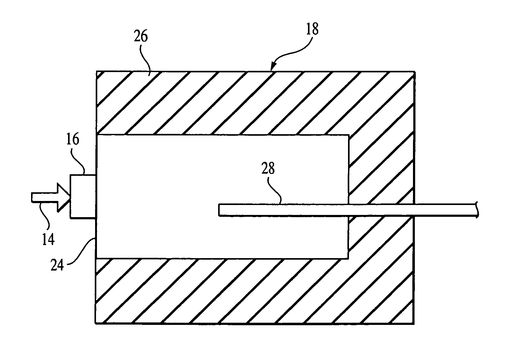
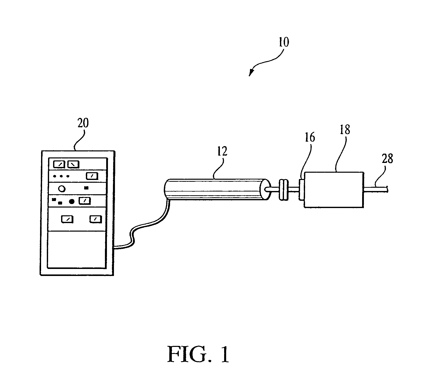
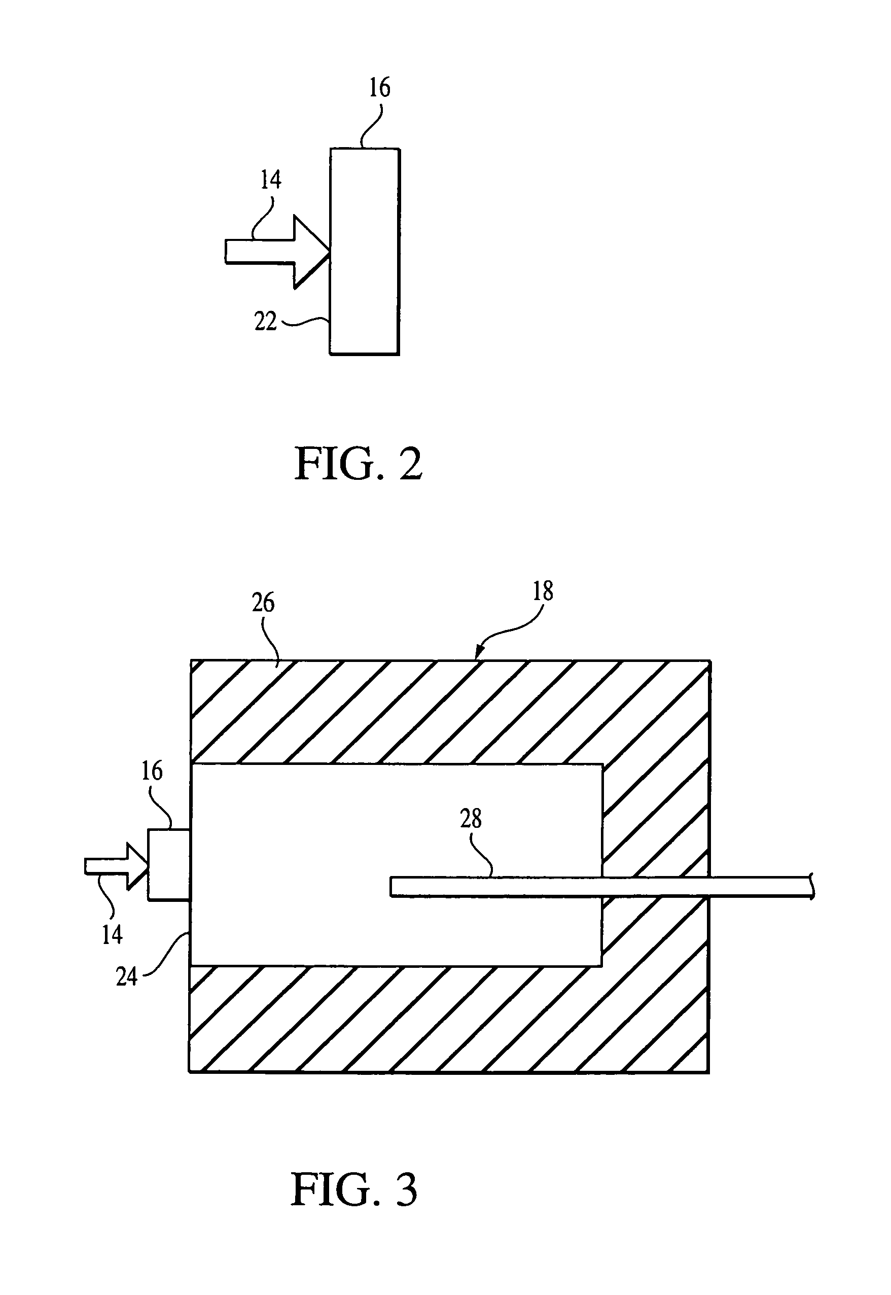
[0010]Turning now to FIG. 1, a neutron generating device in accordance with an embodiment of the present invention is indicated generally at 10, and includes an electron linear accelerator (LINAC) 12 for producing a beam of electrons which is incident 14 incident on an x-ray converter 16. The x-ray converter 16 is attached to a neutron irradiator 18, and produces photons that are directed into the neutron irradiator, where thermal neutrons are generated. The LINAC 12 is connected to a control device 20 a for controlling electron beam 14 output (shown in FIGS. 2 and 3).

[0011]The LINAC 12 of the invention is preferably a commercially available, repetitively pulsed type used, for example, in hospitals for photon radiotherapy. The LINAC 12 has an electron beam energy from approximately 5 to approximately 30 MeV, but preferably in the range of approximately 5-15 MeV, and an electron beam current of approximately 0.1 to 1 mA or 1 to 10 kW for a 10 MeV electron beam.

[0012]Turning to FIG. 2...


PUM


Abstract

Apparatus for generating thermal neutrons includes an electron accelerator for generating an electron beam and a converter for converting the electron beam into photons. A receiving device is provided for receiving the photons and includes a material which provides a photoneutron target for the photons, for producing high energy neutrons in a photonuclear reaction between the photons and the photoneutron target, and for moderating the high energy neutrons to generate the thermal neutrons. The electron beam has an energy level high enough to produce photons of sufficient energy to exceed the photodissociation threshold of the selected target material, but that is sufficiently low as to enable the material to moderate the high energy neutrons resulting from the photonuclear reaction.

Description

[0001]This application claims the benefit of U.S. Provisional Application No. 60 / 289,356, filed May 8, 2001.FIELD OF INVENTION[0002]The present invention generally relates to neutron generators, and more particularly to a neutron generator employing an electron accelerator for producing thermal neutrons.BACKGROUND[0003]There are many industrial and clinical applications requiring a high flux of thermal neutrons. A neutron is considered to be thermal when it is in thermal equilibrium with the surrounding materials. Thermal neutrons have a Maxwellian distribution of energies and can be generally considered to have a kinetic energy less than 1 eV (electron-volt). Examples of industrial applications include neutron radiography and Prompt Gamma Neutron Activation Analysis (PGNAA). Some examples of clinical applications include production of radioactive stents used in the prevention of restenosis following arterial intervention, such as balloon angioplasty, and production of short lived r...

Claims


Application Information

Patent Timeline
Patent Type & Authority Patents(United States)
IPC IPC(8): G21G1/00H05H3/06
CPCH05H3/06
Inventor GAHL, JOHN M.DALE, GREGORY E.
Owner UNIVERSITY OF MISSOURI
Learn More