
Diffusively permeable monolithic biomaterial with embedded microfluidic channels

a monolithic biomaterial, diffusively permeable technology, applied in the direction of prosthesis, biocide, bandages, etc., can solve the problems of limited use, limited use, and limited options, and achieve the effect of facilitating wound healing

Active Publication Date: 2014-03-04
CORNELL RES FOUNDATION INC
View PDF4 Cites 11 Cited by
  • Summary
  • Abstract
  • Description
  • Claims
  • Application Information

AI Technical Summary

Benefits of technology

[0015]Another aspect of the present invention relates to a method of facilitating healing of a cutaneous wound of a mammalian subject. This method involves providing a monolithic biomaterial of the present invention. The monolithic biomaterial is contacted with a cutaneous wound of the mammalian subject. At least one healing agent is then introduced into the primary network of microfluidic channels under conditions effective to allow for convective transport of the healing agent through the microfludic channels and for diffusive transport of the healing agent into the substrate, thereby facilitating healing of the wound.

Problems solved by technology

The poor healing characteristics of cartilage have driven the demand for options to replace or supplement damaged tissue.
Synthetic materials have been employed for this purpose, but issues of biocompatibility and eventual material failure by fatigue or wear ultimately limit their use.
Allografts present an alternative, but their use can be limited by immunological complications, transmission of infectious diseases from the donor, premature resorption of the transplant, and lack of the availability of donor material.
This approach is hindered by the clinical difficulties associated with harvesting donor tissue.
In both the study and treatment of wounds, scientists and doctors lack tools with which to manipulate the wound environment with high spatial and temporal precision.
:S147-155 (1999)) and bone (Vacanti et al., New Eng. J. Med. 344:1511-1514 (2001)); for these systems, limited clinical success has been achieved.
Nonetheless, engineering tissue has been hindered by the lack of sophisticated tools for tailoring the physical and chemical environment of the tissue-forming cells.
While questions of mass transfer are often discussed in tissue engineering context, there is a lack both of tools with which to implement controlled mass transfer in a growing tissue, and of basic design rules for such a control system.
The creation of a synthetic scaffold that provides the appropriate structural and chemical environment to developing cells is a core strength and challenge of the tissue engineering approach.
This post-seeding method has a distinct disadvantage in that the seeding density is typically inhomogeneous, at least initially (Obradovic et al., Aiche Journal 46:1860-1871 (2000)).
This technique can pose challenges due to immunological rejection, resorption, and inaccessibility for detailed study of tissue development.
No technique has yet been presented that allows for fluid motion to be directed along well-defined paths within a material suitable for use as a tissue scaffold.
In general, there is an outstanding challenge to apply microfluidic methods to control the chemical environment of cells in a 3D culture.

Method used


Image

  • Diffusively permeable monolithic biomaterial with embedded microfluidic channels
  • Diffusively permeable monolithic biomaterial with embedded microfluidic channels
  • Diffusively permeable monolithic biomaterial with embedded microfluidic channels

Examples


example 1

Fabrication of a Monolithic Biomaterial

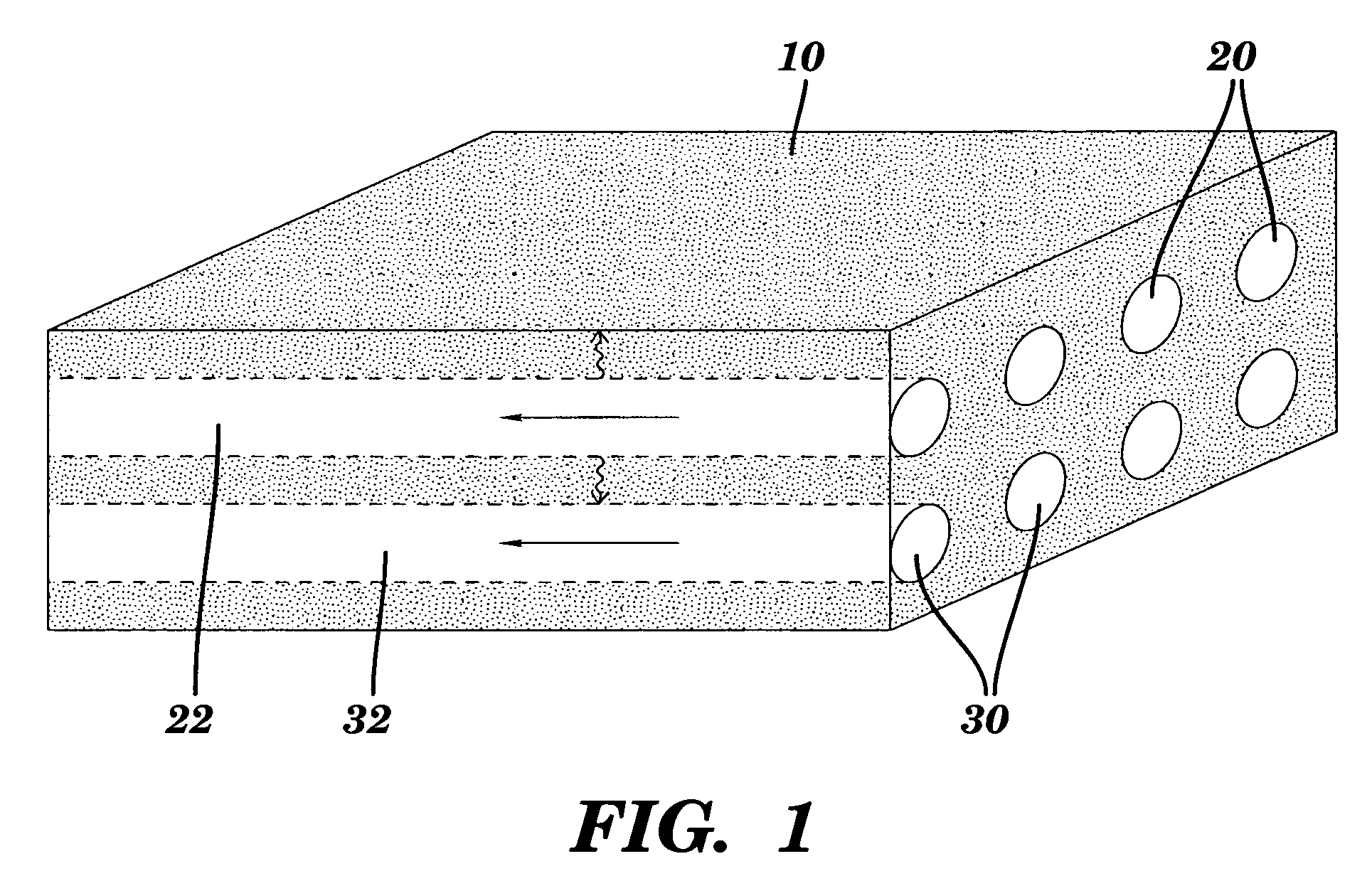
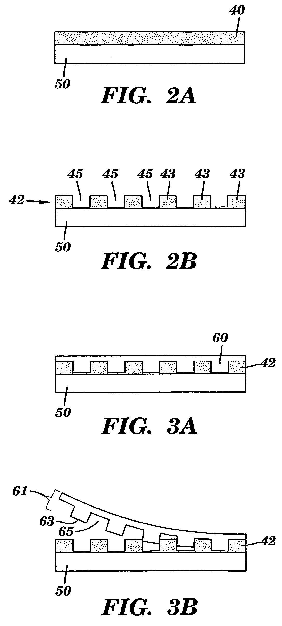
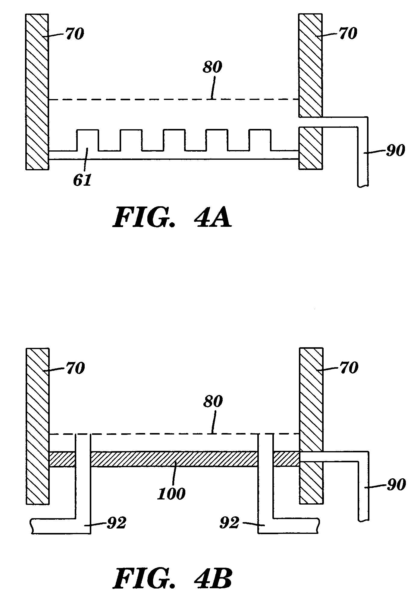
[0114]A monolithic biomaterial was fabricated having a microfluidic system entirely within calcium alginate (4% [w / v]), a versatile hydrogel. As used herein this monolithic biomaterial is also referred to as a “microfluidic biomaterial” and abbreviated as “μFBM.” Control of mass transfer within the ρFBM was demonstrated, and the μFBM was shown to be (i) appropriate for replication of the microstructure, (ii) formable into pressure-tight fluidic structures, and (iii) highly permeable to the diffusion of small and large solutes. The sealed microfluidic structure were formed to have channels that are 100 μm wide by 200 μm deep; sealed channels were formed with cross-sectional dimensions as small as 25 μm×25 μm.

[0115]Three modes of operation have been used to characterize the transfer of solute in μFBMs. In all cases, the device was submerged in a stirred reservoir (200 mL; ur˜1 cm / s) of aqueous buffer in which the solute of interest is dilute (cs,...

example 2

Experimental Methods for Delivery and Extraction of Fluorescent Dyes from μFBM

Fluid Handling

[0123]For all experiments, the μFBM (of Example 1) was submerged in a bath of 200 mL of HEPES-buffered solution with 10 mM CaCl2 in a Petri dish (15 cm in diameter). The dish sat on a magnetic stir-plate that drove a stir-bar at 200 r.p.m. in the bath. The fluid in the bath was changed before each assisted delivery. The assembly was covered by ˜0.5 cm of liquid, and the average flow speed in the liquid was estimated to be, ur˜1 cm / s. This entire assembly sat on the stage of a fluorescence stereoscope.

Assisted Delivery

[0124]In order to deliver fluorescent dye to the μFBM, the inlet of the microfluidic network was connected to an elevated reservoir; the meniscus in the reservoir was maintained ˜10 cm above the sample. A peristaltic pump was attached to the outlet. The flow rates through the system could be regulated between 85 to 150 μL / min (uc=0.4-0.7 cm / s) with the controls of the pump. Solut...

example 3

Analysis of Mass Transfer in μFBM

Mass Transfer Conditions for All Experiments

[0128]The analysis and the operation of the μFBM (of Example 1) are greatly simplified at sufficiently high flow rates, where the bulk concentrations in the reservoir and the channels alone determine the concentration gradients driving the diffusion process. This condition is satisfied when the Biot numbers in both the reservoir and the channels are large, and the Peclêt number in the channels is large. The Biot number is defined as the ratio of the rate of mass transfer into the flow to the rate of diffusive mass transfer through the material, and is

[0129]Bi=kHDs / gel;

the Peclêt number is defined as the ratio of the rate of mass transfer with the flow to the rate of diffusion within the flow, and is

[0130]Pe=uc⁢hDs / liq

(Welty et al., Fundamentals of Momentum, Heat, and Mass Transfer (2000), which is hereby incorporated by reference in its entirety). Here, Ds / gel and Ds / liq are the molecular diffusivities of t...


PUM

PropertyMeasurementUnit
heightaaaaaaaaaa
widthaaaaaaaaaa
thicknessaaaaaaaaaa

Abstract

The present invention relates to a monolithic biomaterial. The monolithic biomaterial has a primary network of convective flow, microfluidic channels that are embedded in a substrate, where the substrate is diffusively permeable to aqueous solutes. The present invention also relates to a method of making the monolithic biomaterial, as well as methods of using the monolithic biomaterial to facilitate healing of a cutaneous wound of a mammalian subject and of regulating cells.

Description

[0001]This application claims priority benefit of U.S. Provisional Patent Application Ser. No. 60 / 619,091, filed Oct. 15, 2004, which is hereby incorporated by reference in its entirety.[0002]This invention was made with government support under grant number N00014-04-1-0652, awarded by the Office of Naval Research, and grant numbers ECS-9876771, ECS 03-35765, and DMR 0520404, awarded by the National Science Foundation. The U.S. Government has certain rights in this invention.FIELD OF THE INVENTION[0003]The present invention relates to a diffusively permeable monolithic biomaterial with embedded microfluidic channels, a method of making the monolithic biomaterial, and methods of using the monolithic biomaterial to facilitate healing of a cutaneous wound of a mammalian subject and to regulate cells.BACKGROUND OF THE INVENTION[0004]Over one million surgical procedures in the United States each year involve bone and cartilage replacement (Langer et al., Science 920:260-266 (1993)). The...

Claims


Application Information

Patent Timeline
Patent Type & Authority Patents(United States)
IPC IPC(8): A61K9/00
CPCA61F13/00068A61F13/00012A61F15/00A61F2002/30766A61F13/00063A61F2002/30677A61F2002/30957A61F2013/00536A61L27/3817A61L27/3839A61F2002/30785A61F2013/00927A61L27/20A61F2310/00365A61F2013/00523A61F13/069A61F2002/2817A61F2/30756C08L5/04
Inventor STROOCK, ABRAHAM D.CABODI, MARIOBONASSAR, LAWRENCE
Owner CORNELL RES FOUNDATION INC
Learn More