
Pleated stent assembly

Inactive Publication Date: 2005-04-28
ELECTROFORMED STENTS
View PDF27 Cites 183 Cited by
  • Summary
  • Abstract
  • Description
  • Claims
  • Application Information

AI Technical Summary

Benefits of technology

[0021] In the preferred embodiment, the medical device of the pleated medical device assembly is a stent. Use of the pleated stent assembly of the present invention has many advantages. The stent of the present invention is co-pleated with the balloon and unpleated with the balloon as the balloon expands within the vessel, essentially eliminating non-uniform stent expansion. Minor subsequent expansion of the stent to fine tune its diameter to properly fit the stent within the lumen is accomplished by expanding both the balloon and the stent with additional pressure in the balloon. Thus, during both the unfolding and fine-tune expanding, there is no tendency for non-uniform expansion.
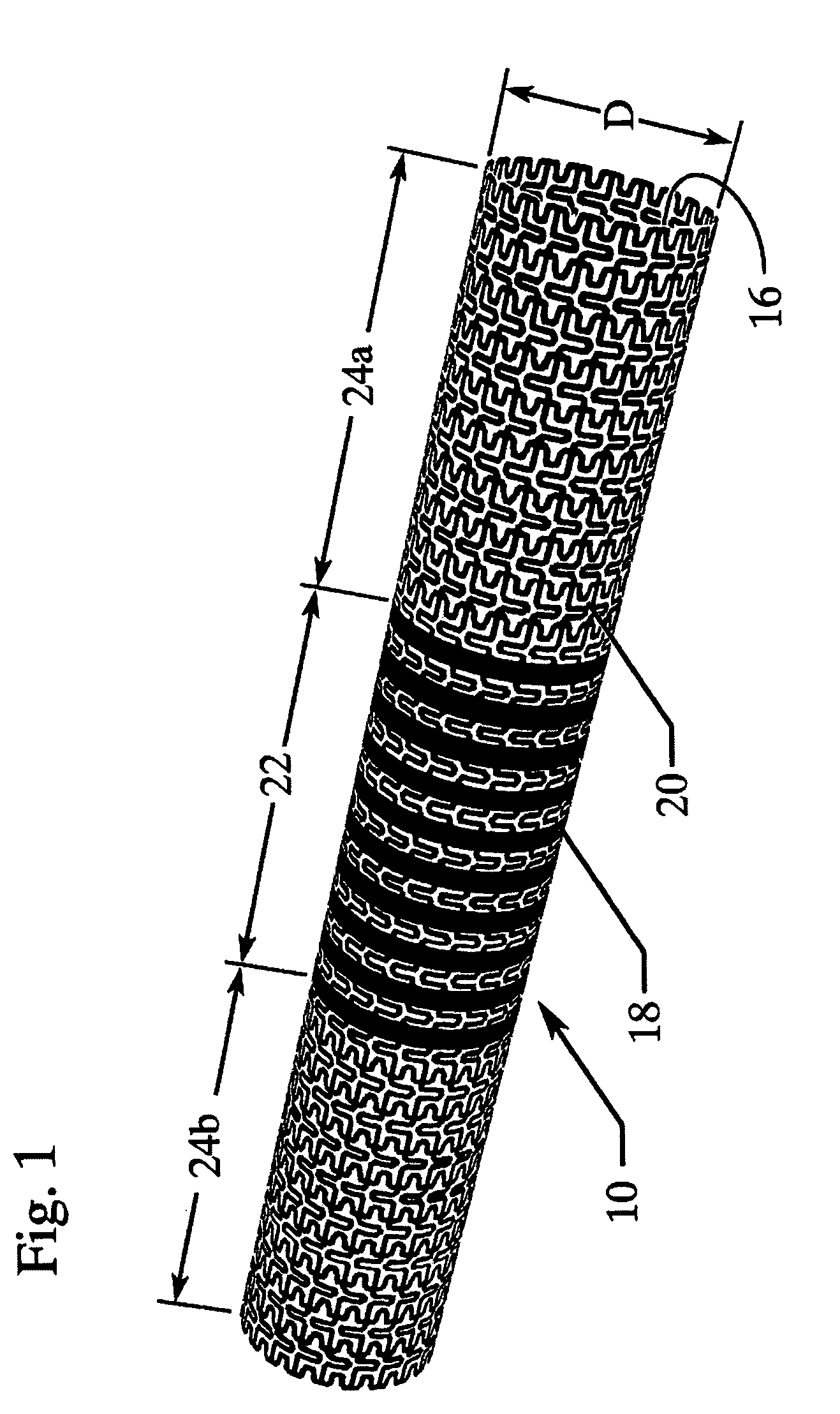
[0023] When used to treat aneurysms, the stent of the present invention preferably comprises a substantially solid body section between two expandable anchor sections. The pleated stent assembly of the present invention can be used to treat neurovascular aneurysms by providing the required combination of (i) flexibility for delivery, (ii) a sufficiently dense wall to cover the aneurysm and exclude blood circulation in the aneurysm and (iii) the ability to properly size the placed stent to fix its location without damage to the artery, a combination not found in currently available stents.
[0024] When used to treat an aneurysm, the stent of the present invention is positioned in an artery at the point of the aneurysm, such that the substantially solid body section of the wall of the stent covers the aneurysm, thereby blocking blood flow to the aneurysm to induce thrombosis in the aneurysm, promote healing and reduce risk of rupture. Deprived of blood circulation, the material in the aneurysm will solidify and the volume of the aneurysm will gradually reduce in volume. Additionally, the lattice-like struts forming the wall of the stent will serve as a platform for growth of new tissue that will bridge the aneurysm, forming a new natural wall for the vessel as the healing process progresses.
[0025] The use of a stent to treat aneurysms in this manner was not possible with prior technology. Use of the pleated stent assembly of the present invention allows the area of the stent that bridges the aneurysm to be solid or nearly solid, thereby excluding the aneurysm from the circulation without the need for coils. Additionally, since the anchor sections of the stent may be balloon expanded, the final placement diameter of the stent may be fine-tuned based on visual angiographic feedback. As a result, appropriate contact between the stent and interior wall of the vessel can be achieved. The stent may be patterned to provide longitudinal flexibility, and since non-compliant balloons are not required, elastic or semi-compliant balloons can be used to improve the longitudinal flexibility of the assembly. As a result of the flexibility of the pleated stent assembly of the present invention, the stent can be tracked through the carotid siphon and placed distal to the carotid siphon. The pleated stent can be used with difficult-to-treat aneurysms of the internal carotid or the basilar artery without most of the drawbacks of existing treatment methods. In cases of aneurysms in skull base locations that are very difficult to reach surgically, use of the pleated stent assembly of the present invention promises to be more effective and safer than prior surgery or coiling methods.

Problems solved by technology

As a result, the surface of the expanded stent has a significant amount of open space.
Conventional stents expanded from a small cylinder to a large cylinder on a typical balloon are non-uniformly expanded due to non-uniform tension in the stent struts generated as the balloon expands by unpleating.
The non-uniform expansion results from the fundamental mismatch between the manner in which the non-compliant balloon expands and the manner in which the stent expands.
Friction between the stent struts and the balloon surface results in non-uniform expansion of the stent.
Non-uniform expansion weakens the stent and increases the size of the openings between the stent struts that may allow tissue of the vessel to prolapse.
For example, although use of stents to treat neurovascular aneurysms has been considered, stents currently available are not suitable.
Substantial open spaces in the walls of expandable stents do not sufficiently cover the aneurysm to block blood flow to the aneurysm.
Solid stents do not have a variable diameter such that there is a high likelihood that the stent would be too large and harm the fragile vessel, or be too small and migrate through the vessel.
Solid stents also do not have the flexibility required for delivery through the carotid siphon to the neurovascular arteries.
Thus, standard stents have not been successful in treating neurovascular aneurysms.
The damage is caused by the initial injury to the brain, as well as delayed complications.
Therefore, aneurysms in survivors of acute subarachnoid hemorrhage have to be treated urgently to prevent repeat rupture and a very high risk of death.
Although it is sometimes possible to identify aneurysms that are at risk before rupture occurs and treat them preventively, this subject is controversial.
It is difficult, if not impossible, to determine if an unruptured aneurysm will in fact rupture, and the balance between the risk of intervention itself, compared to the risk of rupture if the aneurysm is left alone, is unclear.
Although many advances have occurred over the past thirty years to improve the efficacy and safety of the procedure, there remains a risk associated with the craniotomy itself.
Brain exposure and retraction may cause further injury to the brain and additional neurological defect.
There are limitations to the aneurysm coiling technique.
Coiling of aneurysms is a technically demanding procedure, with a long learning process.
In other aneurysms, the packing of the aneurysm is more difficult, and either the neck is left open, or coils protrude into the parent vessel with attendant risk of clot formation and embolism.
Despite such advances, the long-term efficacy of aneurysm coiling remains uncertain.

Method used


Image

  • Pleated stent assembly
  • Pleated stent assembly
  • Pleated stent assembly

Examples


Embodiment Construction

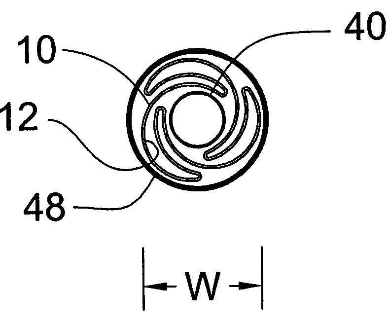
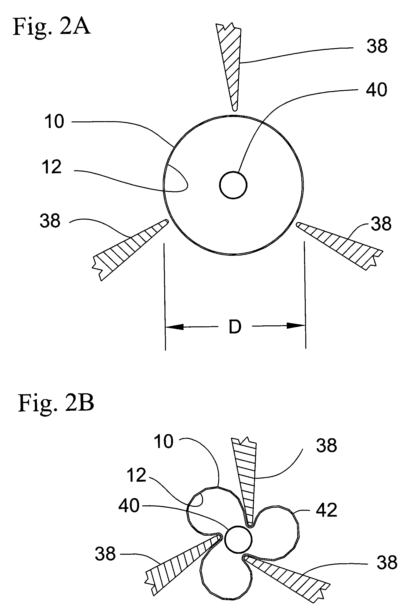
[0030] The present invention is directed to a pleated medical device assembly comprising a tube co-pleated with a balloon. In the preferred embodiment depicted in the drawings, the medical device is a stent 10, as best shown in FIG. 1. Turning to FIGS. 2A, B and C, stent 10 is co-pleated with balloon 12 to form pleated stent assembly 14. Pleated stent assembly 14 comprises stent 10, having original diameter D, and balloon 12, wherein at least a portion of balloon 12 is contained within stent 10. Preferably, balloon 12 extends through the entire length of stent 10. Stent 10 is co-pleated with balloon 12 along longitudinal pleating lines to form a substantially cylindrical pleated tube / balloon assembly 14, having a delivery width W, less than original diameter D, and suitable for intraluminal delivery. Stent assembly 14 may be delivered to the target location in a body vessel using standard techniques well know in the art.

[0031] Once positioned at the desired target location within t...


PUM


Abstract

The present invention is directed to a pleated medical device assembly, preferably a pleated stent assembly, comprising a tube co-pleated with a balloon to a delivery width suitable for intraluminal delivery. Because the tube of the present invention transitions between its original diameter and its delivery diameter by folding and unfolding, rather than by radial contraction and expansion, the wall of the tube of the present invention may be substantially non-expandable, and thus may be substantially solid. The pleated stent assembly of the present invention is particularly suited for the treatment of neurovascular aneurysms.

Description

CROSS-REFERENCE TO RELATED APPLICATIONS [0001] Not Applicable. STATEMENT REGARDING FEDERALLY SPONSORED RESEARCH OR DEVELOPMENT [0002] Not Applicable. BACKGROUND OF THE INVENTION [0003] The present invention is directed to the field of stenting and more specifically to the field of medical and veterinary stents for endovascular treatments. [0004] A stent is a tubular medical device typically inserted into the lumen of a vessel, or other organ, to open the vessel and / or maintain the vessel in an open position to maintain flow within the vessel. Stents are typically introduced to the body percutaneously and delivered intraluminally, via a catheter, to a desired position in the lumen of the vessel. [0005] Stents are generally cylindrical shells comprised of interconnected elements or struts. The pattern of struts on the surface of the cylinder allows the stent to be crimped to a small diameter for delivery and to expand radially from the small delivery diameter to a larger placement dia...

Claims


Application Information

Patent Timeline
IPC IPC(8): A61F2/82
CPCA61F2/844A61F2/91A61F2/915A61F2002/91575A61F2002/91533A61F2002/9155A61F2002/823
Inventor HINES, RICHARD A.ROITBERG, BEN Z.
Owner ELECTROFORMED STENTS
Learn More