
Method for producing cellulose-fiber flat structure

a flat structure and cellulose fiber technology, applied in the field of flat structure production of cellulose fiber, can solve the problems of large specific gravity of glass plates, difficult to reduce in weight, warping, cracking of deposited films, etc., and achieve the effect of favorable surface texture and efficient recovery of fine cellulose fibers

Active Publication Date: 2014-03-04
OJI HLDG CORP
View PDF11 Cites 8 Cited by
  • Summary
  • Abstract
  • Description
  • Claims
  • Application Information

AI Technical Summary

Benefits of technology

[0020]The present invention is able to provide a method of producing a cellulose-fiber flat structure, which can efficiently recover fine cellulose fibers from a dispersion containing fine cellulose fibers having a nano level average fiber diameter, can produce a cellulose-fiber flat structure having a favorable surface texture, and can be applied to continuous processes and the like, as well as providing a cellulose-fiber flat structure obtained using the above method, a cellulose-fiber composite obtained using the cellulose-fiber flat structure, and a method of producing the cellulose-fiber composite.

Problems solved by technology

However, glass plates have a large specific gravity and are difficult to reduce in weight, and also suffer from other drawbacks such as being susceptible to breakage, unable to bend, and requiring a predetermined thickness.
However, these conventional plastic materials for replacing glass have a large coefficient of linear expansion compared with a glass plate, and therefore during the process of depositing a device layer such as a thin film transistor on the substrate at high temperature, problems such as warping, cracking of the deposited film, and semiconductor disconnection tend to occur readily, meaning practical application of such plastic materials has proven difficult.

Method used


Image

  • Method for producing cellulose-fiber flat structure
  • Method for producing cellulose-fiber flat structure
  • Method for producing cellulose-fiber flat structure

Examples


production example 1

Cellulose-Fiber Flat Structure Production 1

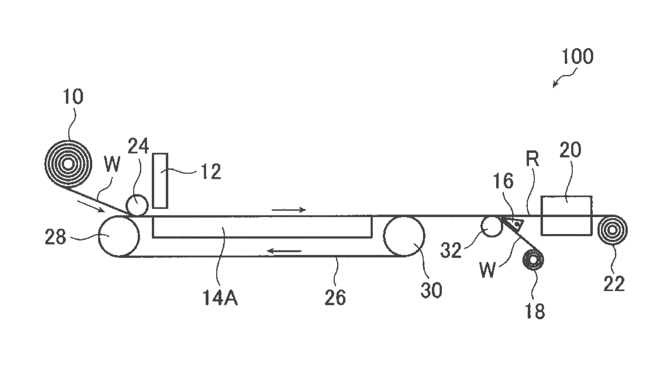
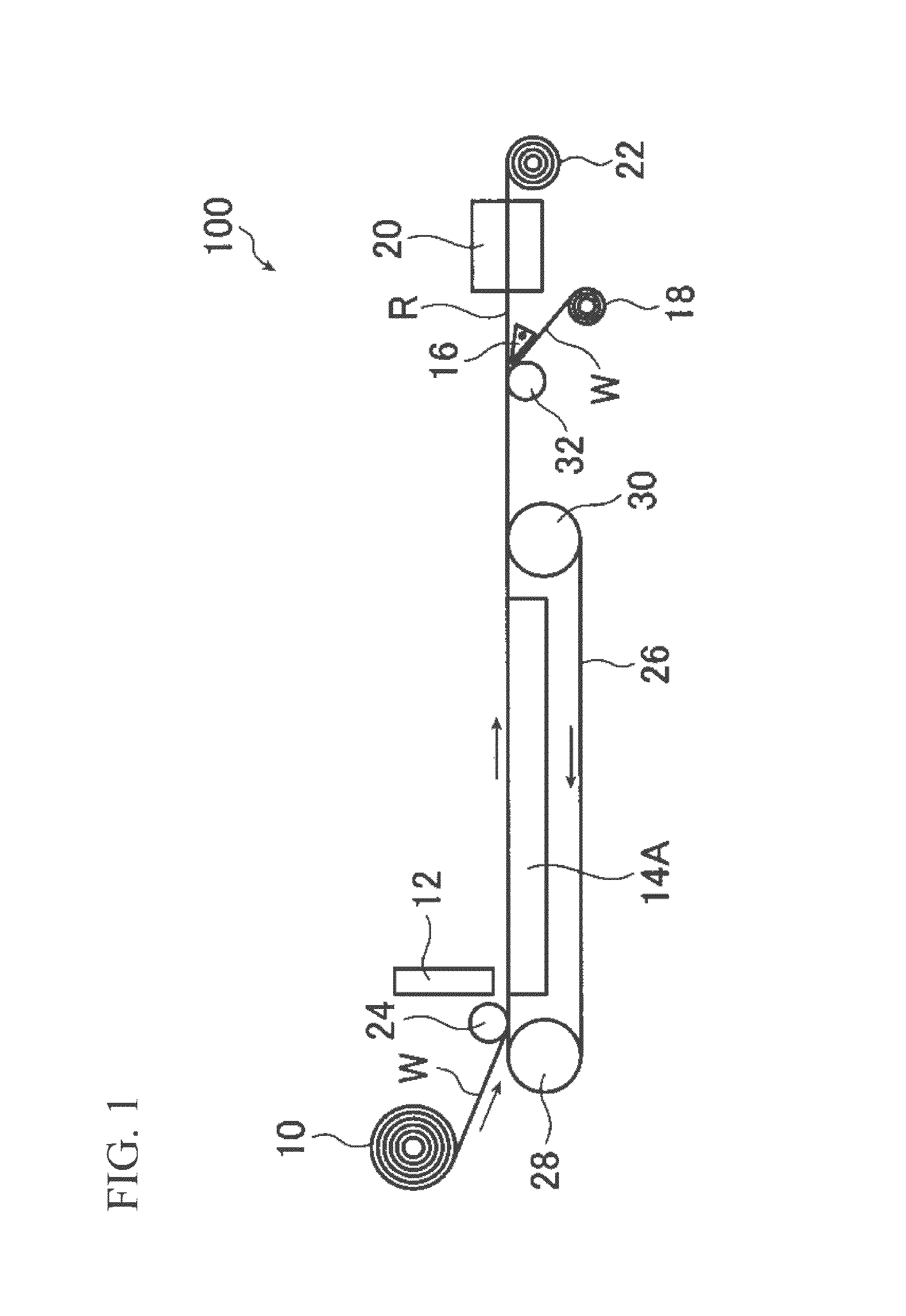
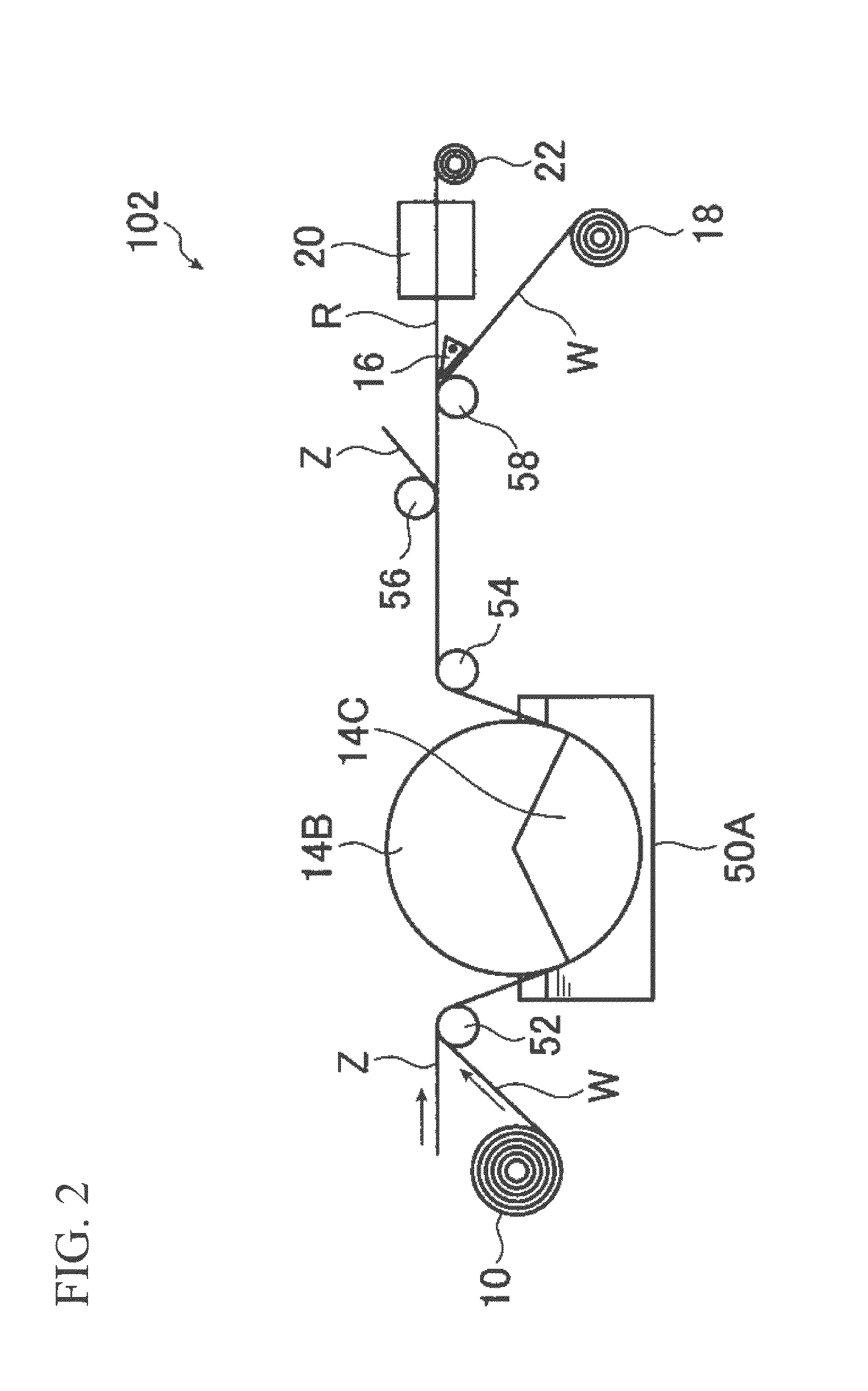
[0236]The filter material described below was fitted in a filter holder for reduced-pressure filtration (KG-90 (diameter: φ90 mm), manufactured by Advantec MFS, Inc.). Subsequently, the fine cellulose-fiber dispersion produced above was diluted with demineralized water to prepare 150 g of a dispersion having a cellulose fiber concentration of 0.13% by weight, and filtering was then started under reduced-pressure conditions (−0.09 MPa). Immediately after starting filtering, 30 ml of 2-propanol was added, and filtering was continued. Following the completion of the filtering operation, the deposit of fine cellulose fibers remaining on top of the filter material was peeled away from the filter material and press-dried for 5 minutes at a temperature of 120° C. and a pressure of 2 MPa, thus obtaining a cellulose-fiber flat structure.

production example 2

Cellulose-Fiber Flat Structure Production 2

[0237]The filter material described below was fitted in a filter holder for reduced-pressure filtration (KG-90 (diameter: φ90 mm), manufactured by Advantec MFS, Inc.). Subsequently, the filter material was wetted with approximately 10 ml of 2-propanol, reduced-pressure filtering was performed until the 2-propanol was no longer visible on the filter material, and the inside of the filtration bell jar was then returned to normal pressure. Subsequently, the fine cellulose-fiber dispersion produced above was diluted with demineralized water to prepare 150 g of a dispersion having a cellulose fiber concentration of 0.13% by weight, and filtering was then started under reduced-pressure conditions (−0.09 MPa). Immediately after starting filtering, 30 ml of 2-propanol was added, and filtering was continued. Following the completion of the filtering operation, the deposit of fine cellulose fibers remaining on top of the filter material was peeled aw...

example 1

[0238]A knitted fabric (average thread thickness: 2.0 d / f (50d / 25f), composition: 70% by weight polyester / 30% by weight nylon (splittable composite fiber), thickness: 370 μm, fabric weight: 180 g / m2) was subjected to a calender treatment to produce a filter material (5025SDY). The thickness of the thus obtained filter material (5025SDY) was 180 μm, and the water permeability was 17.0 ml / m2·s.

[0239]Using the thus obtained filter material, a cellulose-fiber flat structure was produced in accordance with the method described above in the production example 1. The initial tensile modulus of the filter material was 220 MPa. Further, in terms of the surface texture of the cellulose-fiber flat structure, only surface texture derived from the knitted fabric was confirmed (asperity: 45 μm, pitch: 168 μm), and no surface texture derived from the net or the like was confirmed, indicating no transfer of the support texture. The results are shown in Table 1. The dispersion was poured onto the su...


PUM

PropertyMeasurementUnit
diameteraaaaaaaaaa
thicknessaaaaaaaaaa
thicknessaaaaaaaaaa

Abstract

The present invention relates to a method of producing a cellulose-fiber flat structure, the method including obtaining a cellulose-fiber flat structure by filtering a fine cellulose-fiber dispersion containing fine cellulose fibers having an average fiber diameter of 4 to 100 nm, using a filter material having a water permeability of not more than 100 ml / m2·s and an initial tensile modulus of 20 MPa or greater. The present invention is able to produce a cellulose-fiber flat structure by efficiently recovering fine cellulose fibers from a dispersion containing fine cellulose fibers having an average fiber diameter at the nano level. The method of producing a cellulose-fiber flat structure can also be applied to a continuous process.

Description

[0001]This application is the U.S. National Phase under 35 U.S.C. §371 of International Application PCT / JP2011 / 052038, filed Feb. 1, 2011, designating the U.S., and published in Japanese as WO 2011 / 093510 on Aug. 4, 2011, which claims priority to Japanese Patent Application No. 2010-020434, filed Feb. 1, 2010, the content of which is incorporated herein by reference in its entirety.TECHNICAL FIELD[0002]The present invention relates to a method of producing a cellulose-fiber flat structure, and more specifically, relates to a method in which, by filtering a dispersion containing cellulose fibers having a fiber diameter that is narrower than the wavelength of visible light using a prescribed filter material, a cellulose-fiber flat structure composed of fine cellulose fibers can be obtained with good productivity.[0003]Priority is claimed on Japanese Patent Application No. 2010-020434, filed Feb. 1, 2010, the content of which is incorporated herein by reference.BACKGROUND ART[0004]Gene...

Claims


Application Information

Patent Timeline
Patent Type & Authority Patents(United States)
IPC IPC(8): B01D39/16D02G3/00D21H25/00D21H27/08D03D15/00B01D39/18
CPCB01D2323/42D21C9/06D21H15/02B01D71/10B01D69/10B01D67/0004D21H11/18Y10T428/249921B01D2239/10B01D2239/0618B01D39/1607B01D2239/0613Y10T428/298B01D39/18B01D67/00042B01D67/00046
Inventor FUJIWARA, TSUYOSHIOGITA, NAOHIDEKAWAMUKAI, TAKASHI
Owner OJI HLDG CORP
Learn More