
Head for injecting consolidating pressurised fluid mixtures into the ground

a technology of pressurised fluid and head, which is applied in the direction of soil preservation, artificial islands, and fluid removal, etc., can solve the problems of large head loss, multi-helical geometry does not guarantee per se the maximum improvement in performance, and achieves the effect of greater soil disintegration effect, greater efficiency, and reduced power consumption

Active Publication Date: 2014-03-04
TREVI
View PDF8 Cites 0 Cited by
  • Summary
  • Abstract
  • Description
  • Claims
  • Application Information

AI Technical Summary

Benefits of technology

[0009]The main object of the invention is to provide a monitor or injection head having the greatest possible efficiency in terms of penetrative capacity of the jets leaving the monitor, to be more precise to obtain a greater disintegrating effect on the soil to be treated, with the power consumption remaining the same.

Problems solved by technology

This brings about a high head loss, right in the proximity of the outlet from the nozzles, as a result of turbulence which prevents the stream from exiting the nozzles in an ordered manner, i.e. with the velocity vector of the single particle of material exiting oriented according to the main axis of each nozzle.
The procedures by which the fluid passes from the inside to the outside of the monitor are the cause of considerable head losses and are therefore understood not just in terms of increased power consumption but also in terms of a reduced diameter of the column of treated material.
This type of multi-helical geometry does not guarantee per se the maximum improvement in performances with respect to the conformation usually used (i.e. that which generates a turbulent free motion), unless the fundamental parameters for the correct dimensioning of said structure are identified and the inlet and outlet zones of the jet are modified so as to maximise efficiency.
Therefore, the advantage derived from the reduced concentrated losses is limited by the fact that the fluid adopts a very high velocity within the final length, with very high resulting friction losses.
In addition, the presence of ducts, curves and radiuses greatly complicates the overall architecture of the monitor, making the assembly, maintenance and disassembly steps much more complex.

Method used


Image

  • Head for injecting consolidating pressurised fluid mixtures into the ground
  • Head for injecting consolidating pressurised fluid mixtures into the ground
  • Head for injecting consolidating pressurised fluid mixtures into the ground

Examples


Embodiment Construction

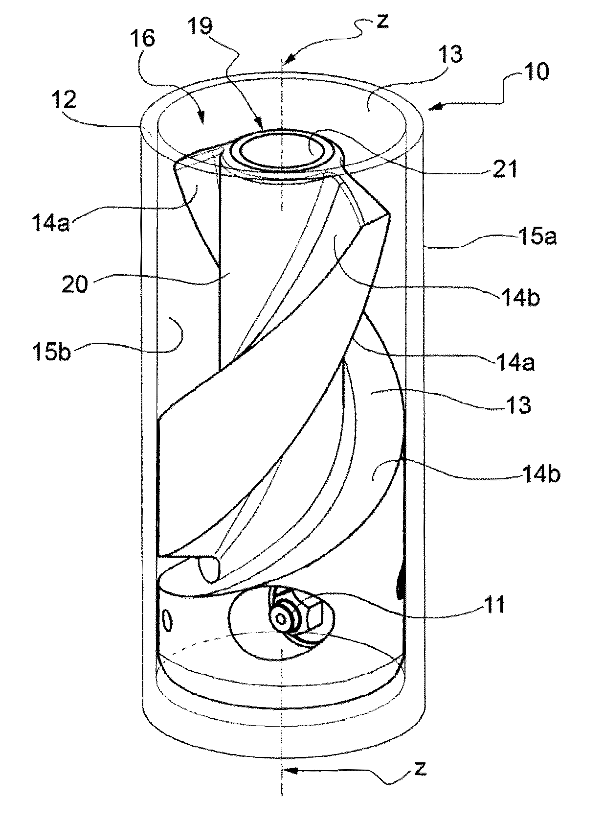
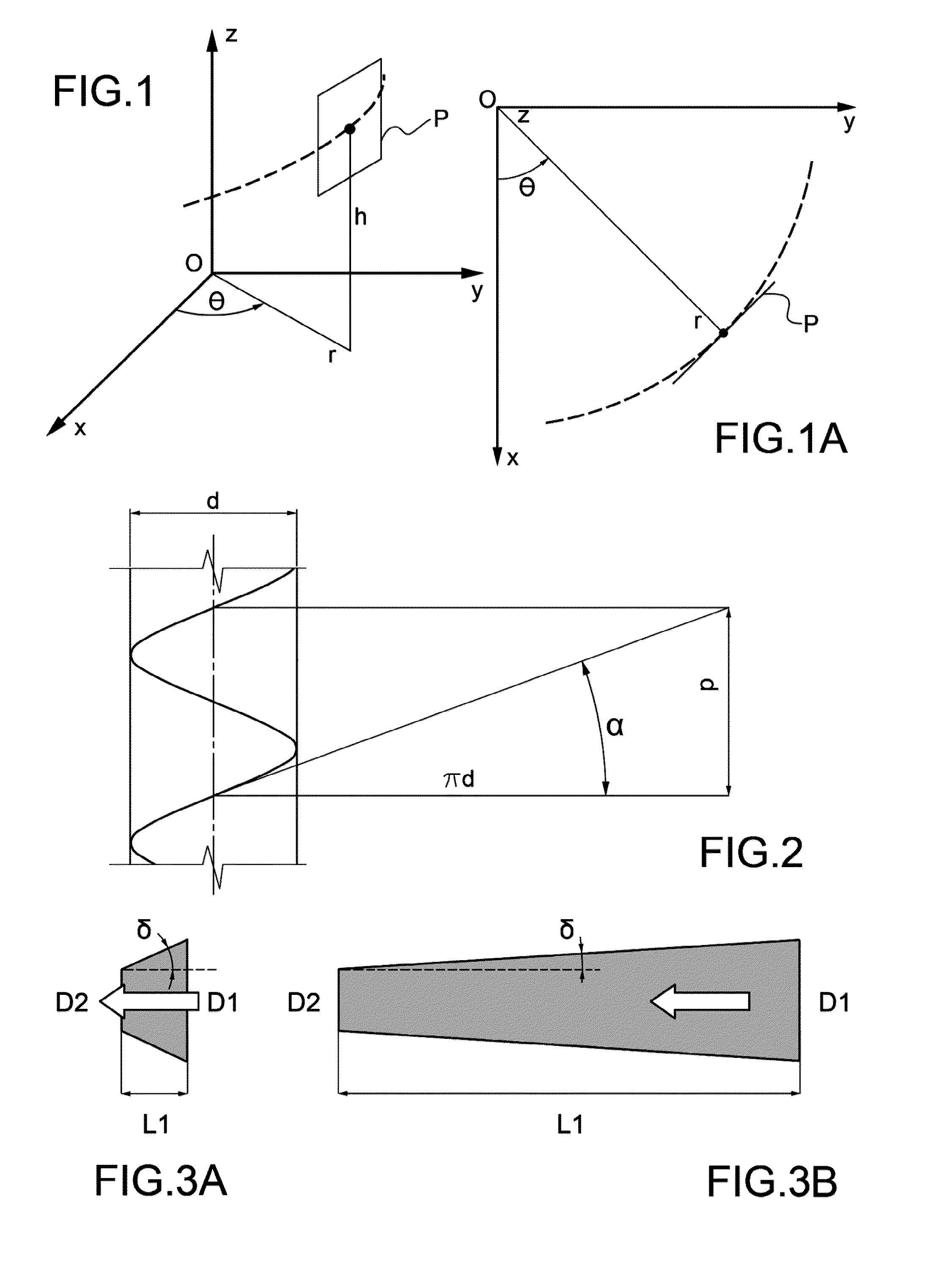
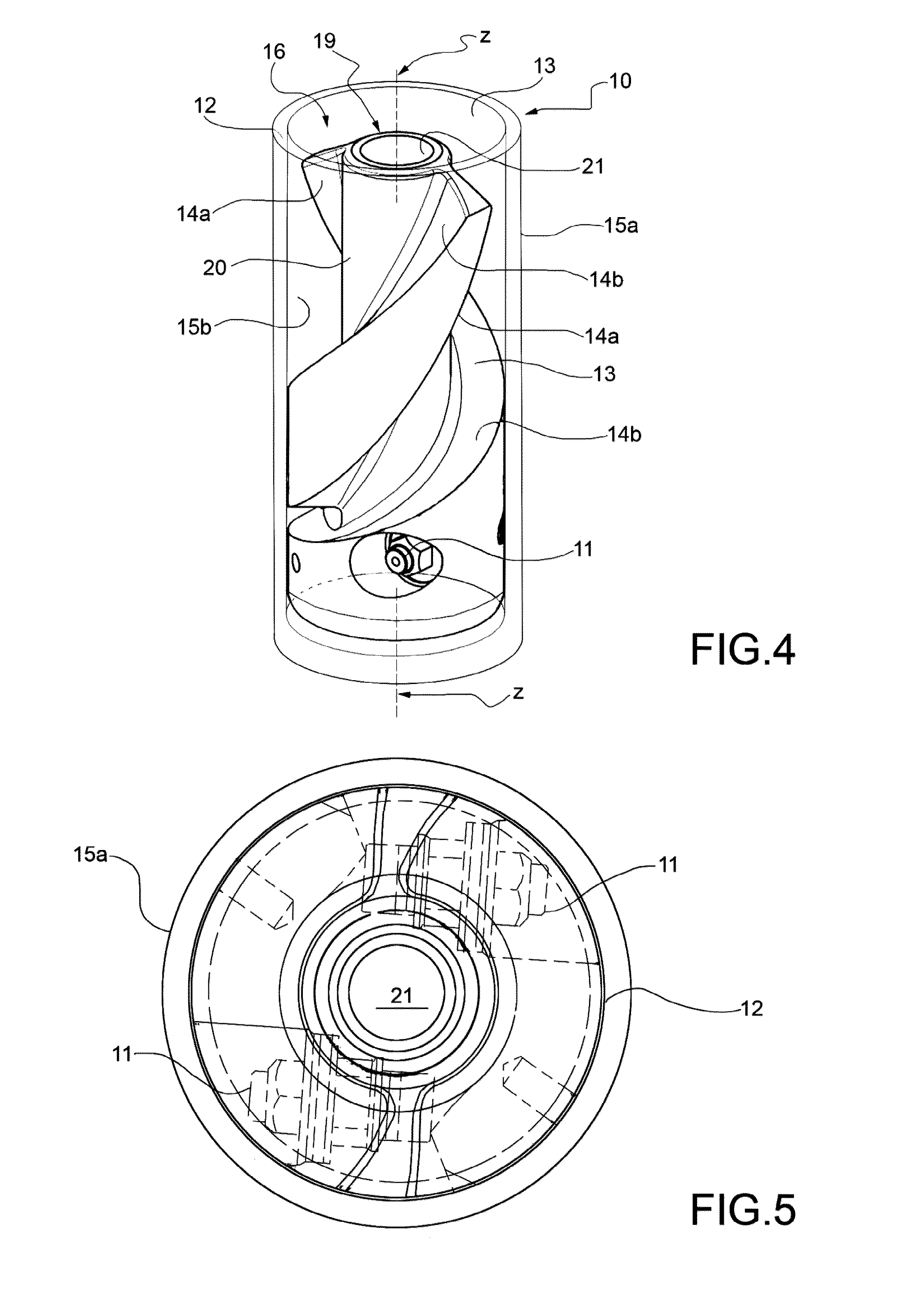
[0023]Before providing a detailed description of a preferred embodiment of the invention, the text hereinafter states the criteria which were carried out in order to achieve the invention and which are all based on the search for the maximum efficiency of the jet. In this respect, an energy analysis was carried out on the fluid stream in motion in the monitor, analysing the head losses. The following have emerged from these analyses, in view of the conditions imposed by the architecture of the monitor:[0024]inlet of the stream predominantly vertically or parallel to the axis of the monitor,[0025]outlet of the stream predominantly orthogonally with respect to the axis of the monitor, and[0026]the presence of a central duct, within the monitor, which is to be left free for the passage of the cooling fluid from the head of the rod,

the path which the fluid has to take within the monitor in order to obtain the greatest possible efficiency (or the minimum head loss) is a helical path. It ...


PUM


Abstract

A head includes an outer cylindrical body with at least one upper inlet for fluids, at least one outlet side nozzle and at least one helical duct having a helical central line. The duct connects the upper inlet to the nozzle and imparts the fluid flowing through it a helical motion about the longitudinal axis of the outer body towards the nozzle. The helical duct is progressively tapered towards the nozzle and includes a terminal length of the duct which is radiused to the nozzle in a tapered manner, both when viewed in cross-sectional planes parallel to the longitudinal axis and tangent to the helical central line, as well as when viewed in cross-sectional planes perpendicular to the longitudinal axis.

Description

[0001]This application claims benefit of Serial No. TO2010A000613, filed 15 Jul. 2010 in Italy and which application is incorporated herein by reference. To the extent appropriate, a claim of priority is made to each of the above disclosed applications.[0002]The present invention relates to a high-efficiency head for injecting consolidating pressurised fluid mixtures into the ground in order to form consolidated soil portions.BACKGROUND ART[0003]The techniques known as “jet grouting” are used to form columnar structures of artificial conglomerate in the ground. These techniques are based on the mixing of particles of the soil itself with binders, usually cement mixtures, which are injected at high pressures through generally small radial nozzles formed in an injection head (commonly referred to as a “monitor”), fixed in the proximity of the lower end of a string of tubular rods which is rotated and withdrawn towards the surface. At the bottom of the string of rods, under the monitor...

Claims


Application Information

Patent Timeline
Patent Type & Authority Patents(United States)
IPC IPC(8): E02D3/12
CPCE02D3/12E02D3/126
Inventor SACCANI, CESARE
Owner TREVI
Learn More