Suture sleeve and a method for manufacturing a suture sleeve

a technology of suture sleeves and sutures, which is applied in the field of suture sleeves, can solve the problems of reducing the gripping force of the suture wire, destroying the function and the difficulty of properly fixing the lead inside the suture sleeve, so as to reduce the tightening force of the suture wire, enhance the gripping force between the inner surface of the suture sleeve and the outer surface of the lead, and reduce the gripping force of the a suture sleeve and suture sleeve and suture sleeve and suture sleeve and suture sleeve suture sleeve and suture sleeve and suture sleeve and manufacturing method, which is applied in the field of suture sleeve, and achieve the effect of sleeve tightening for

Active Publication Date: 2014-02-11
ST JUDE MEDICAL
View PDF11 Cites 12 Cited by
  • Summary
  • Abstract
  • Description
  • Claims
  • Application Information

AI Technical Summary

Benefits of technology

[0008]It is an object of the invention to provide an improved suture sleeve by means of which the gripping force between the inner surface of the suture sleeve and the outer surface of the lead can be enhanced while maintaining the tightening force in the suture wire, alternatively maintaining the gripping force between the inner surface of the suture sleeve and the outer surface of the lead while lowering the tightening force in the suture wire.
[0014]The stiffening protuberances in the bottom of each suture groove are preferably confined to the suture grooves only. Normally, the suture sleeve is formed as one uniform body comprised of only one elastic material and the stiffening protuberances are accordingly formed as a thicker material layer in the area radially outside of each grip enhancing projection having a different radius of curvature in cross section than the rest of the suture groove. Accordingly, the cross sectional shape of the suture sleeve at each suture groove will be non-circular, which will have to effect that the tightening force from the suture wire will be concentrated to the stiffening protuberances and transferred radially inwardly to the respective grip enhancing projection and the lead. However, it is also possible to position small embedment items, preferably of a more rigid material than the rest of the suture sleeve, in the mold before forming of the suture sleeve. In this way the stiffening protuberances may be formed of not only a thicker material but also of a material having e.g. a larger strength.
[0015]To further increase the concentration of the tightening forces from the suture wire to the grip enhancing projections, it is conceivable to arrange weakening zones in the areas between adjacent grip enhancing projections and stiffening protuberances. In a hereinafter described and illustrated embodiment, these weakening zones are provided with weakening grooves or recesses such that the wall of the suture sleeve is provided with a thinner material thickness in these weakening zones and hence will be easier deformed when tightening the suture wire.

Problems solved by technology

However, due to small lead dimensions and glossy outer surfaces of the leads having a low coefficient of friction, it can sometimes be difficult to fixate the lead properly inside the suture sleeve, since the suture wire cannot be tightened excessively due to the risk of cutting through tissue as well as the suture sleeve itself.
A lead which is not properly fixated to the tissue may accidentally be pulled out, which can be devastating for its function since its inner end normally is in engagement with an organ to be controlled, treated or monitored.
However, the effect, in terms of increased gripping force, of the suture sleeves disclosed according to the prior art, is not quite satisfactory.

Method used


Image

  • Suture sleeve and a method for manufacturing a suture sleeve
  • Suture sleeve and a method for manufacturing a suture sleeve

Examples


Embodiment Construction

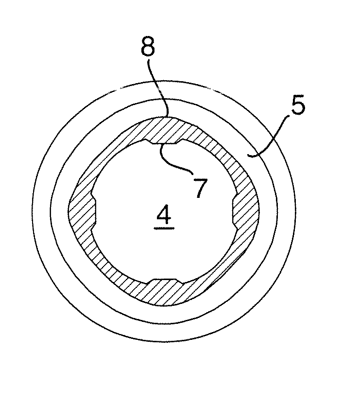
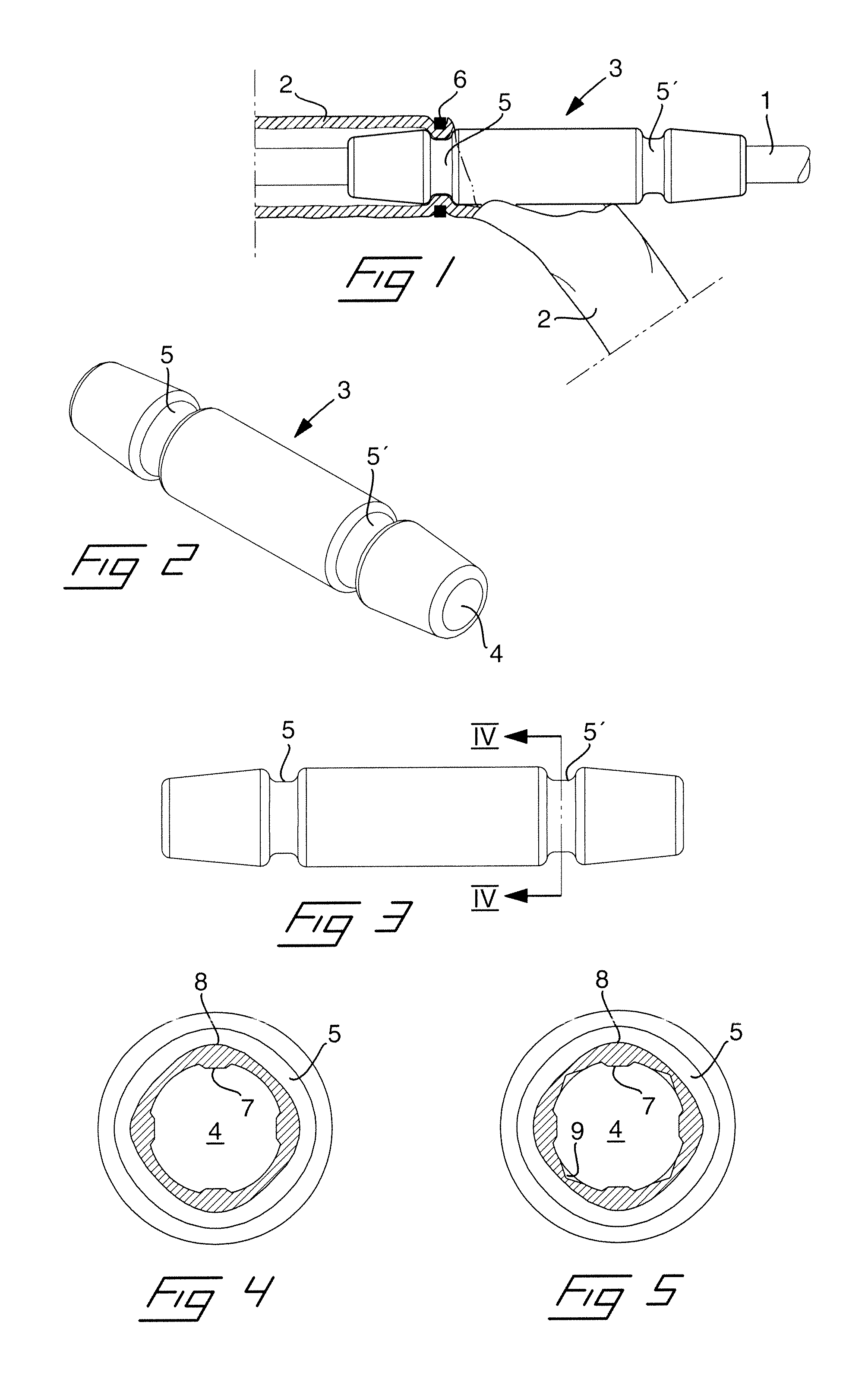
[0022]Reference is first made to FIG. 1 in which is illustrated implantation of a lead 1 through a vein 2 by means of a suture sleeve 3 according to the invention. The suture sleeve is illustrated more in detail in the perspective view and the side view of FIGS. 2 and 3, respectively, and is formed as an elongated tube of an elastic material provided with an inner through bore 4 which extends in the longitudinal direction of the sleeve. On the outside the suture sleeve is formed with two circumferential and longitudinally spaced suture grooves 5, 5′. When using the suture sleeve for implanting a lead into a vein 2, as illustrated in FIG. 1, an incision is made in the vein and subsequently the lead 1 together with an end portion of the suture sleeve 3 is inserted through the incision into the vein, as is illustrated in FIG. 1.

[0023]By tying a suture wire 6 around the vein 2 and the suture sleeve 3 in a region at one of the suture grooves 5, the suture sleeve will be fixated to the ve...


PUM

PropertyMeasurementUnit
widthaaaaaaaaaa
radius of curvatureaaaaaaaaaa
areaaaaaaaaaaa

Abstract

A suture sleeve for securing a medical implantable lead in position in relation to a human or animal body, has a tubular body of a resilient material defining a through bore in the longitudinal direction of the suture sleeve and being formed with one or more longitudinal spaced, circumferential suture grooves on the outside and two or more grip enhancing projections around the inner circumference of the through bore in at least an area radially inward of a suture groove. The suture sleeve is formed with two or more stiffening protuberances in the bottom along the circumference of the suture groove such that the bottom of the suture groove deviates from circular as seen in cross section. The, stiffening protuberances are positioned radially outside of the respective grip enhancing projections on the inside. A method for manufacturing such a suture sleeve is also described.

Description

BACKGROUND OF THE INVENTION[0001]1. Field of the Invention[0002]The invention relates to a suture sleeve for securing a medical implantable lead in position in relation to a human or animal body, of the type having a tubular body of a resilient material defining a through bore in the longitudinal direction of the suture sleeve and being formed with one or more longitudinal spaced, circumferential suture grooves on the outside and two or more grip enhancing projections around the inner circumference of the through bore in at least an area radially inward of a suture groove.[0003]The invention also relates to a method for manufacturing of a suture sleeve.[0004]2. Description of the Prior Art[0005]Medical implantable leads are used for various purposes in order to connect the inner of a human or animal body with the outside or a device arranged subcutaneously. As examples of such leads can be mentioned electrical leads for monitoring and / or controlling of the function of a heart by mea...

Claims


Application Information

Patent Timeline
Patent Type & Authority Patents(United States)
IPC IPC(8): A61N1/05
CPCA61M2025/0286A61M25/0012A61M25/02A61N1/057A61M25/04A61N2001/0582A61M2025/028A61M25/0009
Inventor HELGESSON, MARCUS
Owner ST JUDE MEDICAL
Why Eureka
Try Eureka