
Ergometric training device

a training device and stationary piece technology, applied in the direction of ergometry, cardiovascular exercise devices, sports equipment, etc., can solve the problems of time-consuming and complex, and the known methods are particularly time-consuming, and achieve the effect of simplifying the measuring devi

Active Publication Date: 2014-02-04
WATTBIKE IP
View PDF26 Cites 12 Cited by
  • Summary
  • Abstract
  • Description
  • Claims
  • Application Information

AI Technical Summary

Benefits of technology

This patent describes a solution for detecting the movement of a rider's feet and the force they apply to the pedals. This is important for accurately measuring the power output of the rider during training. The solution uses magnets and magnetic sensors to detect the movement of the feet and calculate the force they apply. This data is then displayed in real-time, allowing the trainer to see how the rider is using their feet during training. Additionally, the patent describes how the solution can be used to adjust the air resistance of the training device based on the rider's needs. Overall, this makes the training experience more immersive and helps the rider improve their power output.

Problems solved by technology

These known exercise and measuring apparatuses aim to measure the force or torque expended by the person training by various methods, which are nevertheless often time-consuming and complex.
The known methods are particularly time-consuming if a differentiated view of various sections of the process, namely a breakdown between the two feet (or the two hands on hand-operated devices), is desired.

Method used


Image

  • Ergometric training device
  • Ergometric training device
  • Ergometric training device

Examples


Embodiment Construction

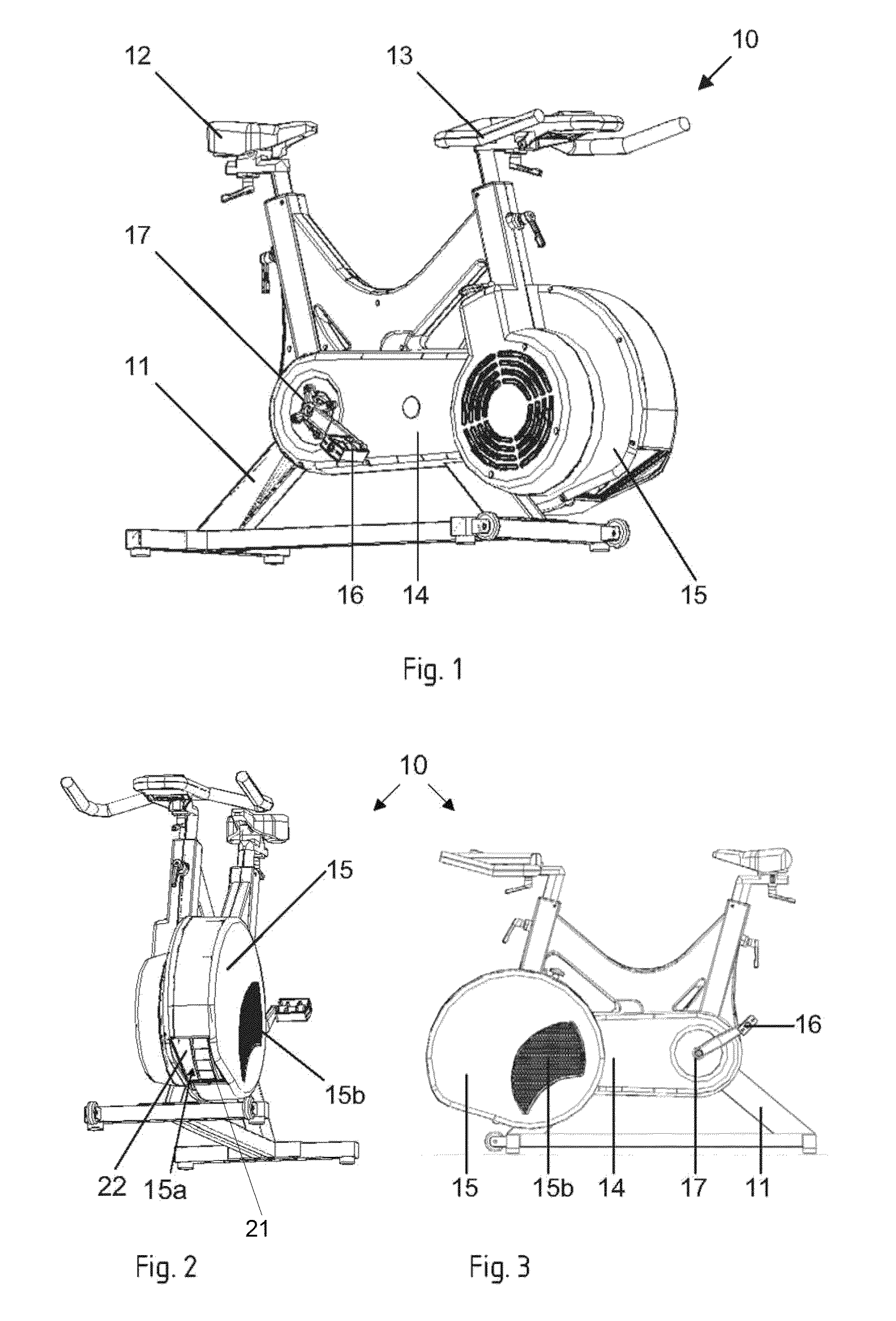
[0035]The exemplary embodiment discussed in what follows concerns a stationary ergometric bicycle training device, which is shown in FIGS. 1 to 3 in various views. The training device 10 can be used e.g. as a home exercise machine, as a training device in a fitness studio or for use in elite sport, or also in the medical field.

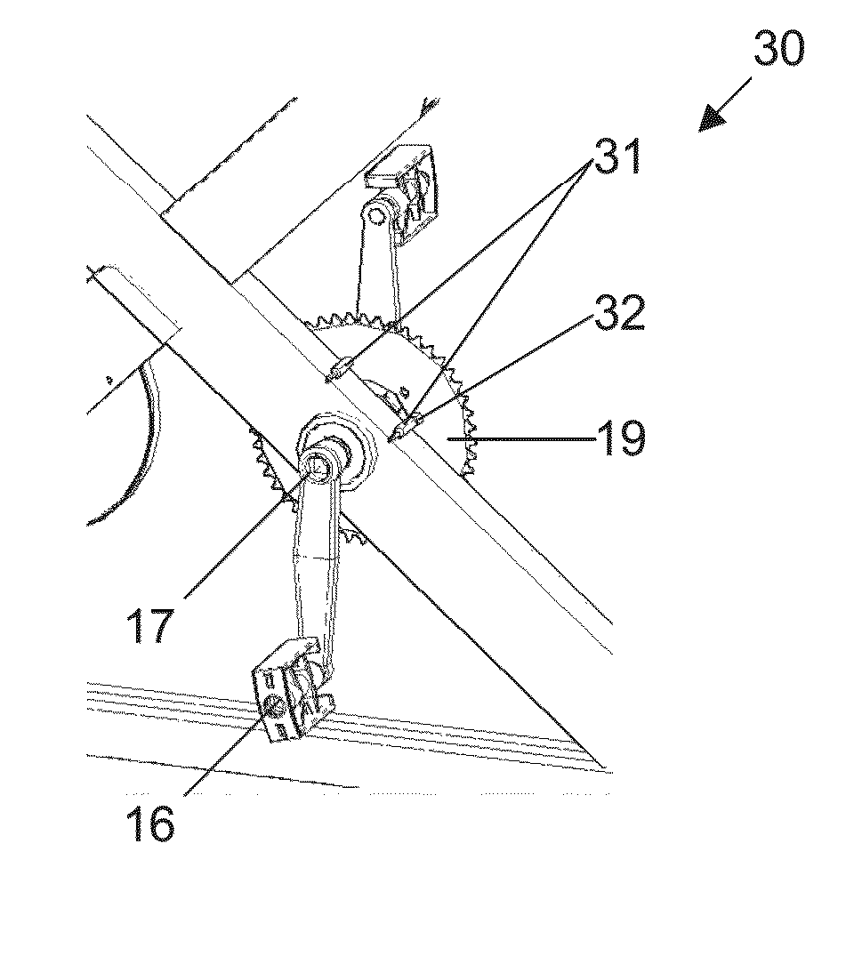
[0036]The training device 10 has a bicycle-like rack frame 11 with a seat 12 and handlebars 13, the positions of each of which can be set, while a training cycle is nevertheless fixed. In the foot area is located a housing 14, which in its front area has a wheel guard 15, as well as a pair of pedals 16. The pedals 16 are attached to a pedal shaft 17 in the known way and are connected via a gear mechanism with resistance mechanisms, which are accommodated into the wheel guard 15 as described below.

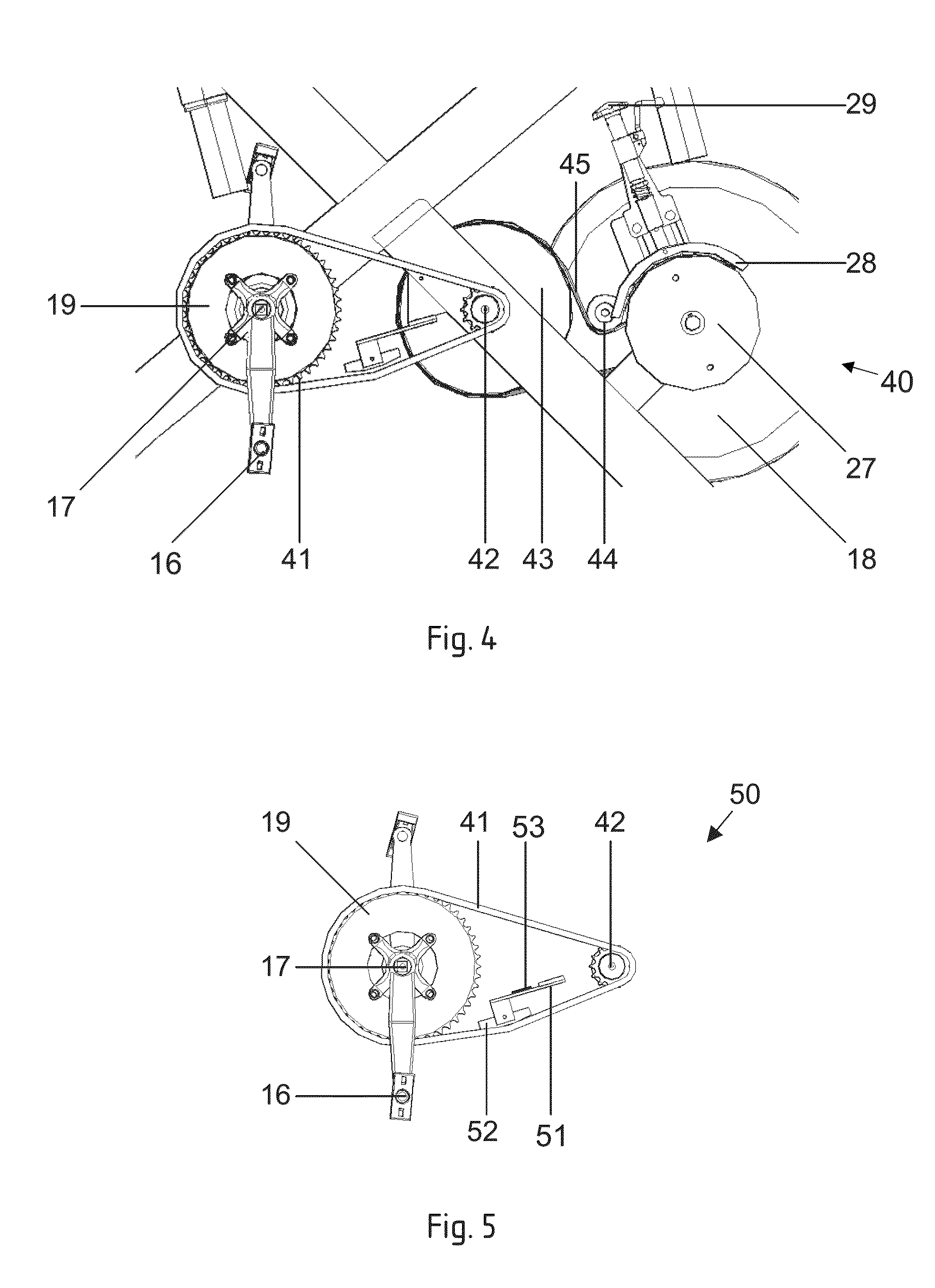
[0037]With reference to FIG. 4, the gear mechanism 40 is, in the shown exemplary embodiment, a combination of two traction drives, namely a gear drive with a belt dri...


PUM


Abstract

A stationary, ergometric exercise apparatus including a hand / foot-operated drive with two drive elements that are operated alternately and a measuring device for measuring the drive force applied to the drive force includes a measuring device for measuring the angular position of the drive, having a pair of sensor devices which are arranged in positions opposite to each other relative to a wheel that is joined to the drive so as to be synchronous in motion with it, which positions each correspond to a position in motion of a load alternation between the two drive elements. A computer receives the signals from the force measuring device and calculates the temporal progress of the drive force, as well as variables that can be derived from it, and alternately output a dedicated right or left limb reading for a person in training depending on the load alternation notified by the measuring device.

Description

CROSS REFERENCE TO RELATED APPLICATIONS[0001]The present application is a U.S. National Stage Application of PCT Application Serial No. PCT / AT 2008 / 000306, filed on Aug. 28, 2008, which claims priority from Austrian Patent Application Serial No. A 1363 / 2007, filed on Aug. 30, 2007 and Austrian Patent Application Serial No. A 1364 / 2007, filed on Aug. 30, 2007, all of which are incorporated by reference in their entireties.BACKGROUND OF THE INVENTION[0002]The invention concerns an ergometric, stationary piece of exercise apparatus with a manually-operated (by hand or foot) drive with two drive elements that are operated alternately, wherein the drive is joined to a flywheel by a gear mechanism, as well as to a measuring unit for measuring the drive force applied to the drive, or the torsional force (torque) related to the drive force, and a measuring device for measuring the position in motion, in particular angular position, of the drive. The drive elements are preferably pedals, sim...

Claims


Application Information

Patent Timeline
Patent Type & Authority Patents(United States)
IPC IPC(8): A63B69/16A63B71/00A63B22/06
CPCA61B5/222A63B22/0007A63B2022/0005A63B2071/0652A63B2220/51A63B21/225A63B22/0605A63B2220/16A63B2022/0658A63B24/00A63B21/0088A63B21/005A63B22/0056A63B22/0005
Inventor BACANOVIC, MILANADAMOVIC, DUSAN
Owner WATTBIKE IP
Learn More