
Apparatus for forming microscopic recesses on a cylindrical bore surface and method of forming the microscopic recesses on the cylindrical bore surface by using the apparatus

a cylindrical bore surface and apparatus technology, applied in the direction of manufacturing tools, metal-working machine components, transportation and packaging, etc., can solve the problems of failure to improve productivity, difficult to regularly form the microscopic recesses, and the need for disposable masking sheets

Active Publication Date: 2014-02-04
NISSAN MOTOR CO LTD
View PDF20 Cites 6 Cited by
  • Summary
  • Abstract
  • Description
  • Claims
  • Application Information

AI Technical Summary

Benefits of technology

The present invention provides an apparatus and method for forming microscopic recesses on a circumferential surface of a workpiece. The apparatus is capable of forming the microscopic recesses with high accuracy, improving productivity and saving production costs. Additionally, the apparatus is capable of forming the microscopic recesses at a predetermined press contact load by canceling influence of a centrifugal force.

Problems solved by technology

However, in the shot blasting process of the conventional art as described above, it is difficult to regularly form the microscopic recess, and the operations of attaching and removing the masking sheet are inevitably required.
This leads to failure of improvement in productivity.
In addition, the use of the disposable masking sheet requires increased costs for a masking sheet material and adhesives, as well as costs of forming the through-holes in the masking sheet each time upon conducting the microscopic recess-forming process.
This results in significant increase in production cost for production of the circumferential surface having the microscopic recesses.

Method used


Image

  • Apparatus for forming microscopic recesses on a cylindrical bore surface and method of forming the microscopic recesses on the cylindrical bore surface by using the apparatus
  • Apparatus for forming microscopic recesses on a cylindrical bore surface and method of forming the microscopic recesses on the cylindrical bore surface by using the apparatus
  • Apparatus for forming microscopic recesses on a cylindrical bore surface and method of forming the microscopic recesses on the cylindrical bore surface by using the apparatus

Examples


first embodiment

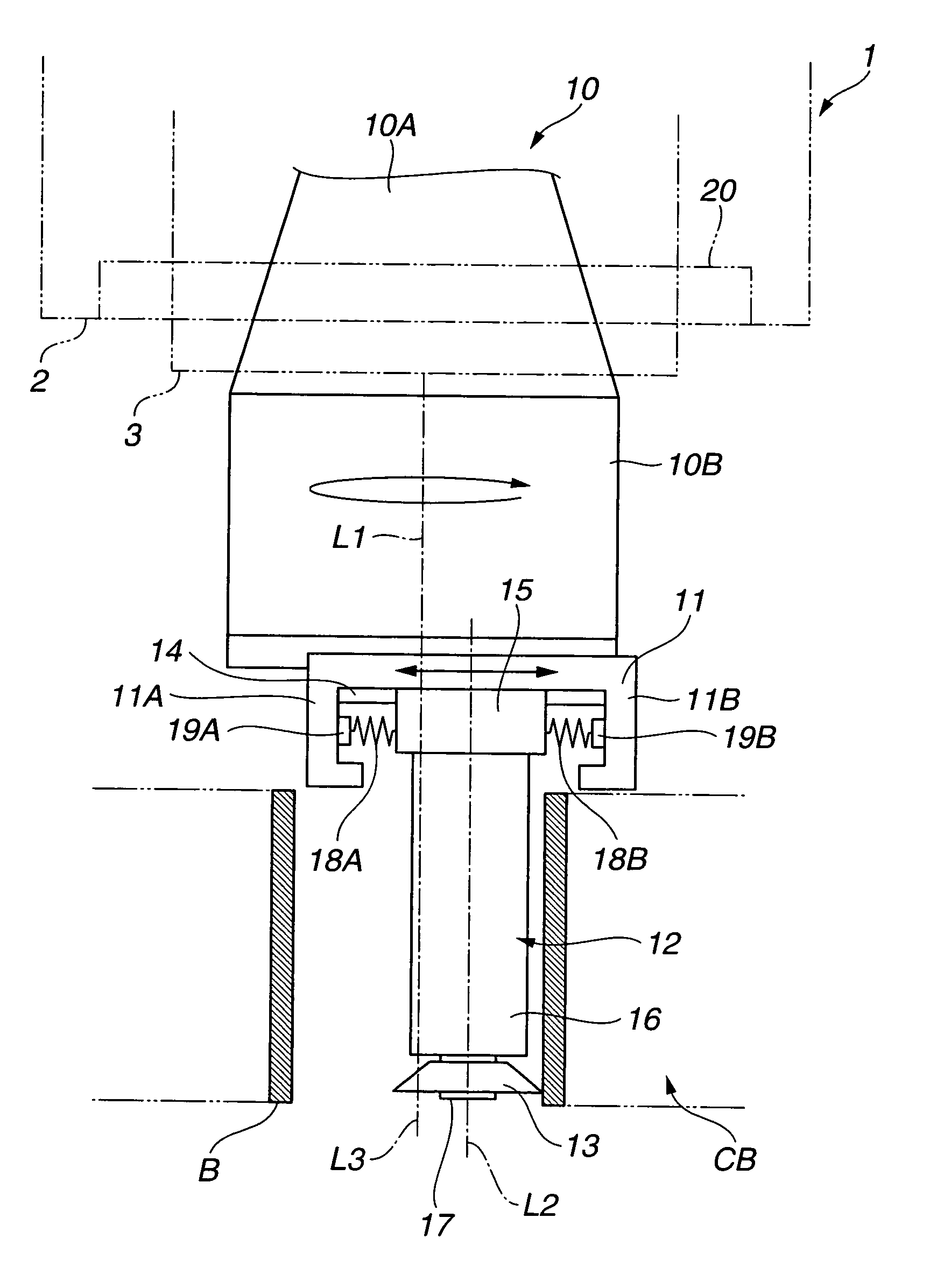
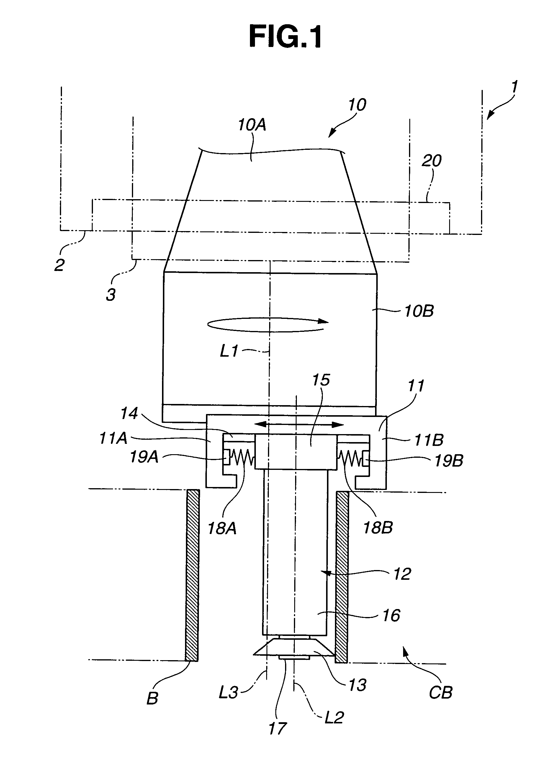
[0070]As is understood from the above explanation, apparatus 1 of the first embodiment and the method of forming the microscopic recesses by using apparatus 1 can provide microscopic recesses on the circumferential surface of cylinder bore B of cylinder block CB with high efficiency and high accuracy. Further, form roller 13 can be in press contact with the circumferential surface of cylinder bore B at the press contact load of the predetermined value. Therefore, it is possible to omit previous works for the circumferential surface of cylinder bore B which must be conventionally performed with high accuracy before forming the microscopic recesses thereon. This realizes significant reduction in the number of production steps and the production cost.

[0071]Further, by using first load generating member 18A that generates the load to be applied to form roller 13 in the advance direction with respect to the circumferential surface of cylinder bore B and second load generating member 18B ...

fifth embodiment

[0088]In apparatus 400 of the fifth embodiment as explained above, counterweight 116 and form roller support 12 with form roller 13 are moved in the opposite directions perpendicular to rotation axis L1 of tool holder 110 to each other, whereby an amount of rotation unbalance of tool holder can be eliminated. Accordingly, substantially the entire load generated by hydraulic cylinder 116A can act as the press contact load at which form roller 13 is pressed against the circumferential surface of cylinder bore B. This serves for precisely controlling the press contact load to thereby form the microscopic recesses on the circumferential surface of cylinder bore B with enhanced accuracy.

[0089]Further, apparatus 400 of the fifth embodiment and the method of forming the microscopic recesses by using apparatus 400 can provide microscopic recesses on the circumferential surface of cylinder bore B of cylinder block CB with high efficiency and high accuracy. Further, even when the microscopic ...

sixth embodiment

[0095]As illustrated in FIG. 11, apparatus 500 of the sixth embodiment includes spring 119 that serves as the load generating member for form roller support 12, and motor 120 that serves as the drive for form roller support 12. Motor 120 also serves as the counterweight for adjusting rotation balance of tool holder 110. Motor 120 is secured to upper table 114 and reciprocatively moveable along guides 117, 117 in the direction perpendicular to rotation axis L1 of tool holder 10.

[0096]In this embodiment, spring 119 is a compression coil spring. Spring 119 is disposed between motor 120 and a side wall of tool holder 110 so as to generate a load which is applied to form roller support 12 in a direction of advance of form roller 13 with respect to the circumferential surface of cylinder bore B. Specifically, spring 119 generates a spring force that acts as a load which is applied to form roller support 12 through motor 120, upper and lower tables 114 and 111 and gear 115 such that form r...


PUM

PropertyMeasurementUnit
rotation axisaaaaaaaaaa
centrifugal forceaaaaaaaaaa
movementaaaaaaaaaa

Abstract

An apparatus for forming recesses on a circumferential surface that defines a cylindrical bore in a workpiece includes a tool holder disposed coaxially with the cylindrical bore; a form roller support retained on the tool holder; a form roller rotatably supported on the form roller support, the form roller including projections on an outer circumferential surface thereof which are configured to form the recesses on the circumferential surface that defines the cylindrical bore in the workpiece. A control assembly is configured to control the form roller support such that the form roller is allowed to be in press contact with the circumferential surface that defines the cylindrical bore in the workpiece at a press contact load of a predetermined value on the basis of a centrifugal force which is exerted on the form roller support and the form roller during rotation of the tool holder.

Description

BACKGROUND OF THE INVENTION[0001]The present invention relates to an apparatus for forming microscopic recesses on a circumferential surface that defines a cylindrical bore in a workpiece and comes into sliding contact with a counterpart, and a method of forming microscopic recesses on the circumferential surface thereof by using the apparatus. More specifically, in order to reduce friction occurring on the circumferential surface, the present invention relates to an apparatus for forming microscopic recesses as oil retention portions on the circumferential surface, for instance, a cylinder bore surface of a cylinder block of an engine for automobiles, a cylinder bore surface of a compressor, a sliding surface of a cylindrical bore of a slide member, a bearing surface of a cylindrical bore of a sliding bearing and the like, and relates to a method of forming microscopic recesses on the circumferential surface by using the apparatus.[0002]Conventionally, upon forming microscopic rece...

Claims


Application Information

Patent Timeline
Patent Type & Authority Patents(United States)
IPC IPC(8): B23G5/00B23Q17/00B23B51/00B23P15/16B23D77/00
CPCC21D7/04C21D7/08B24B39/02B21H7/18Y10T408/85Y10T29/496Y10T408/854Y10T29/49771
Inventor TAKASHIMA, KAZUHIKOUEHARA, YOSHITAKAOTA, MINORU
Owner NISSAN MOTOR CO LTD
Learn More