Lighting device, headlamp apparatus and vehicle using same
a technology of headlamps and lighting devices, which is applied in the direction of electric variable regulation, process and machine control, instruments, etc., can solve the problems of abnormality detection units b>56/b> being erroneously operated, failure of lighting devices, etc., and achieve the effect of preventing abnormal output voltage from increasing
- Summary
- Abstract
- Description
- Claims
- Application Information
AI Technical Summary
Benefits of technology
Problems solved by technology
Method used
Image
Examples
first embodiment
[0064]A lighting device of the present embodiment shares the basic configurations with the conventional lighting device 1′ shown in FIG. 18. The same configurations and functions as those of the conventional lighting device 1′ shown in FIG. 18 will be described first.
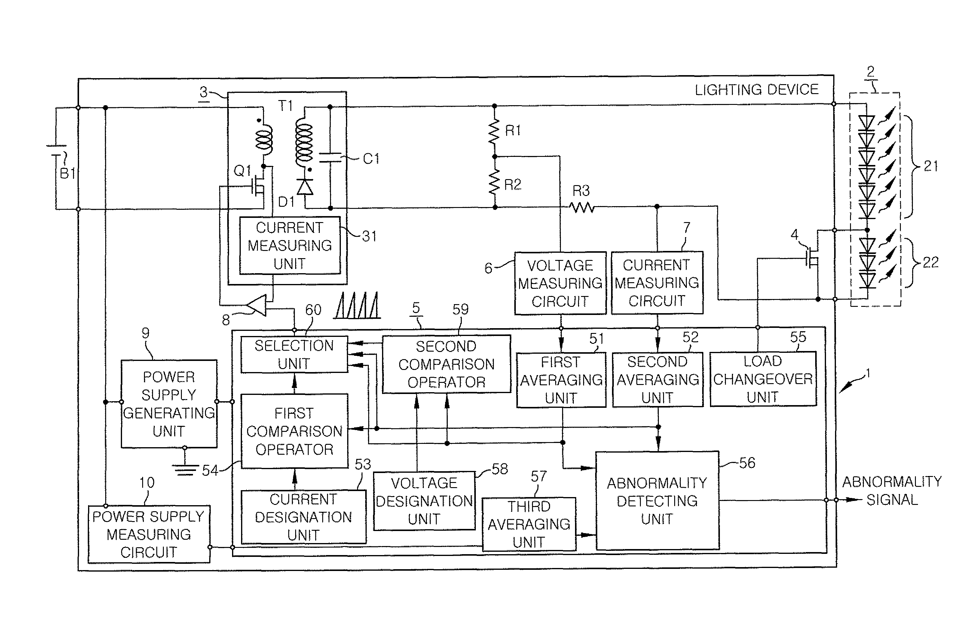
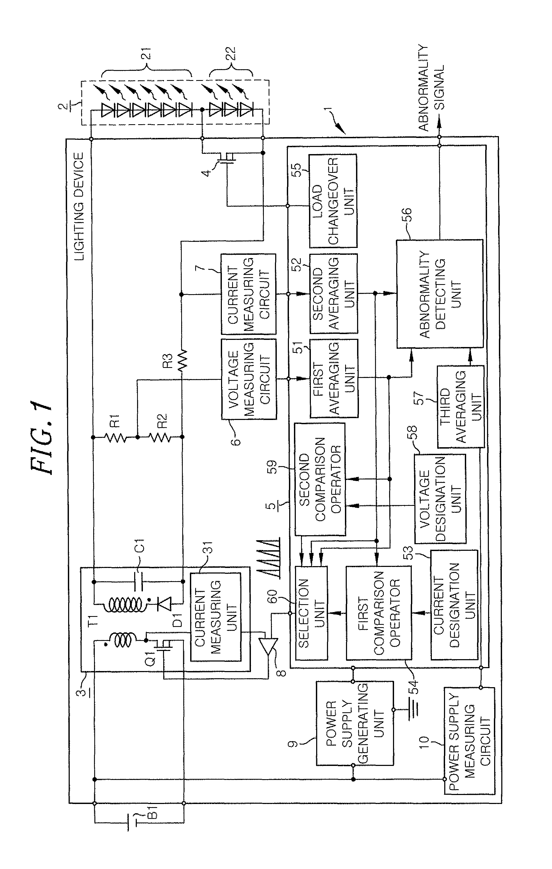
[0065]Referring to FIG. 1, the lighting device 1 in accordance with the present embodiment is designed to turn on loads 2 including a plurality of (e.g., nine, in the present embodiment) LEDs 21 and 22 serially-connected by applying a DC voltage to the loads 2. In the present embodiment, it is assumed that the lighting device 1 is installed in a motor vehicle. Among the LEDs 21 and 22 forming the loads 2, the six anode-side LEDs 21 are used as crossing headlights (also called low-beam headlamps) and the three cathode-side LEDs 22 are used as curvelights. The curve lamps referred to herein are so-called cornering lights. The curve lamps are auxiliary lights that turn on when a motor vehicle runs along a curved road with ...
second embodiment
[0124]The lighting device 1 of the present embodiment differs from the lighting device 1 of the first embodiment in that the power converting unit 3 is controlled in a BCM (Boundary Conduction Mode).
[0125]Referring to FIG. 8, the lighting device 1 of the present embodiment includes a drive circuit (DC) 61 having an RS flip-flop inserted between the output terminal of the comparator 8 and the switching element Q1 and a signal generating unit 62 for outputting an on-signal to the drive circuit 61. The drive circuit 61 has a set terminal to which the signal generating unit 62 is connected and a reset terminal to which the comparator 8 is connected. The signal generating unit 62 outputs an on-signal when the secondary coil current of the transformer T1 becomes zero (discharged). The secondary coil current becoming zero is detected by the current measuring unit 31 by using the decrease in the drain voltage of the switching element Q1 and is notified to the signal generating unit 62 as a ...
third embodiment
[0152]The lighting device 1 of the present embodiment differs from the lighting device 1 of the second embodiment in that, as shown in FIG. 13B, there is an additional step of stopping the drive signal (step F36) when the output voltages are greater than the voltage designated value (step F35). Moreover, the lighting device 1 of the present embodiment is designed to return to the constant current control if a specific time (e.g., 10 ms) lapses after the switching to the constant voltage control (step F33) or if the output currents reach the switching current value (e.g., 0.4 A) (step F34). In FIG. 13B, the step of detecting the drive frequency (step F31) and the step of detecting the sudden change in the load status from the consecutive increase in the drive frequency (step F32) are the same as described above in the second embodiment.
[0153](a), (b) and (c) of FIG. 14 show the changes of the output voltages, the output currents and the drive frequency of the switching element Q1 in ...
PUM
 Abstract
Description
Claims
Application Information
 - R&D
- Intellectual Property
- Life Sciences
- Materials
- Tech Scout
- Unparalleled Data Quality
- Higher Quality Content
- 60% Fewer Hallucinations
Browse by: Latest US Patents, China's latest patents, Technical Efficacy Thesaurus, Application Domain, Technology Topic, Popular Technical Reports.
© 2025 PatSnap. All rights reserved.Legal|Privacy policy|Modern Slavery Act Transparency Statement|Sitemap|About US| Contact US: help@patsnap.com


