Generation of a frequency comb and applications thereof

a frequency comb and frequency technology, applied in the field of measuring the properties of semiconductors, can solve the problems of increasing noise, difficult fabrication, and presently a lower resolution limit of 10 nm, and achieve the effect of improving the accuracy at which the dopant concentration of a depletion region is measured

Inactive Publication Date: 2013-12-03
TRIAD NAT SECURITY LLC
View PDF3 Cites 12 Cited by
  • Summary
  • Abstract
  • Description
  • Claims
  • Application Information

AI Technical Summary

Benefits of technology

[0014]Benefits and advantages of the present invention include, but are not limited to, the generation of a microwave frequency comb wherein each of the frequencies in the comb have sub-Hz linewidths, and the accuracy at which the dopant concentration of a depletion region is measured is substantially improved using 50 or more harmonics of the comb.

Problems solved by technology

These methods provide adequate coupling at frequencies up to several GHz, but the coupling region is significantly larger than the tunneling junction which increases the noise.
Tip electrodes having radii of curvature less than 10 nm are difficult to fabricate; therefore, 10 nm is presently a lower limit for resolution in measurements that are performed using SCM.

Method used


Image

  • Generation of a frequency comb and applications thereof
  • Generation of a frequency comb and applications thereof
  • Generation of a frequency comb and applications thereof

Examples


example

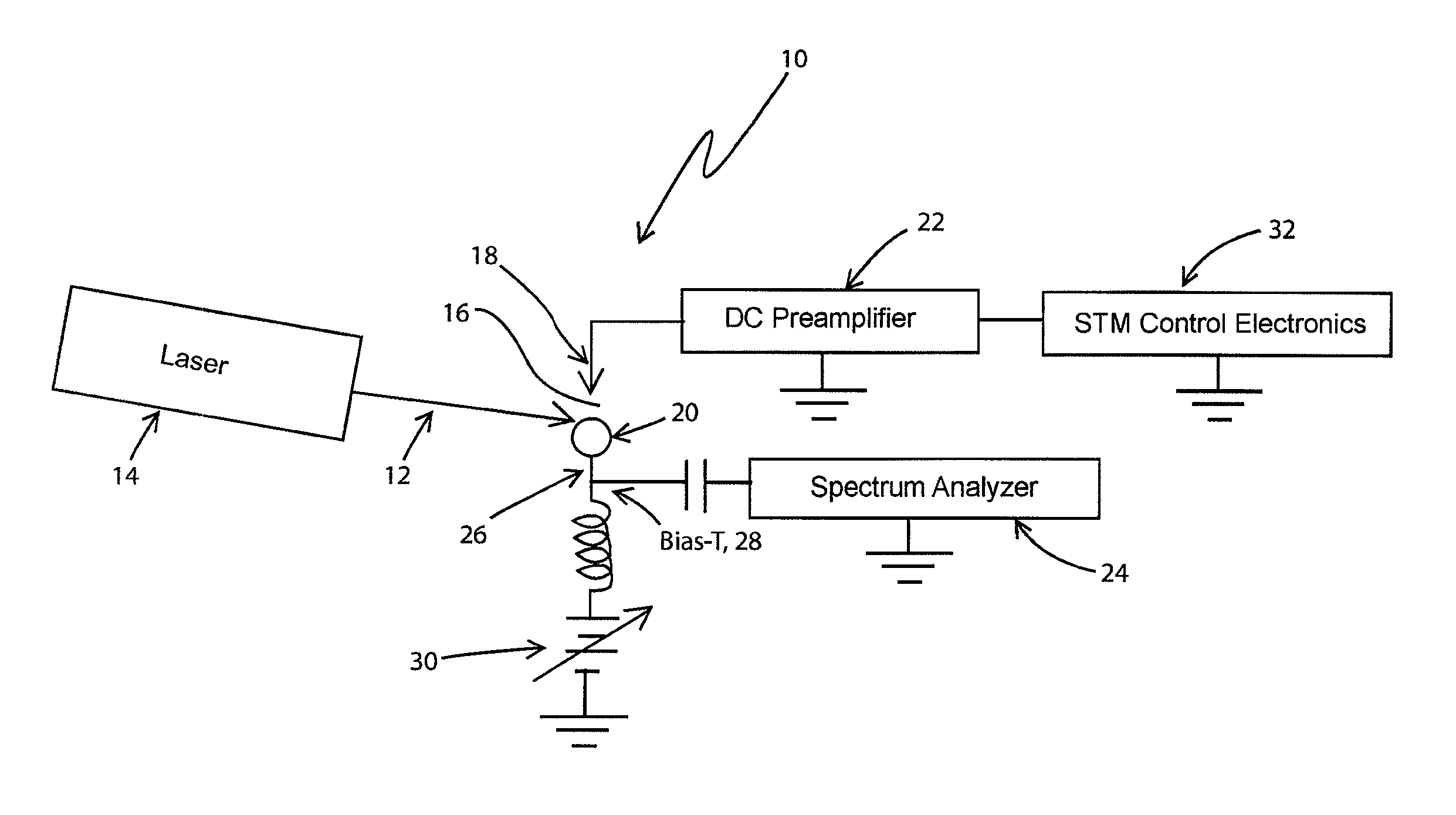
[0042]In the following EXAMPLE, the microwave frequency comb is used measure the nanoscale dopant profile of semiconductors:

[0043]A negative or positive DC bias voltage applied to the tip electrode of a STM causes a depletion layer at the surface of an n-type or p-type semiconductor sample, respectively. In what follows, n-type semiconductors will be described, but the application to p-type semiconductors is straight forward to one having skill in the semiconductor art.

[0044]The close proximity of tip 18 to semiconductor sample 20 causes depletion layer, 34, to have an approximately hemispherical shape as shown in FIG. 6. As the DC bias is made more negative, radius, 36, of the depletion layer increases, as a function of the density of major carriers at outer surface, 38, of the hemisphere. Thus, if the capacitance of the depletion layer is determined as a function of the applied DC bias, the average density of major carriers at each hemispherical surface may be calculated, from whi...


PUM


Abstract

Apparatus for generating a microwave frequency comb (MFC) in the DC tunneling current of a scanning tunneling microscope (STM) by fast optical rectification, caused by nonlinearity of the DC current vs. voltage curve for the tunneling junction, of regularly-spaced, short pulses of optical radiation from a focused mode-locked, ultrafast laser, directed onto the tunneling junction, is described. Application of the MFC to high resolution dopant profiling in semiconductors is simulated. Application of the MFC to other measurements is described.

Description

CROSS-REFERENCE TO RELATED APPLICATIONS[0001]The present application claims the benefit of U.S. Provisional Patent Application No. 61 / 537,809 for “Generation of a Frequency Comb and Applications Therefor” which was filed on Sep. 22, 2011, the entire contents of which is hereby specifically incorporated by reference herein for all that it discloses and teaches.STATEMENT REGARDING FEDERAL RIGHTS[0002]This invention was made with government support under Contract No. DE-AC52-06NA25396 awarded by the U.S. Department of Energy. The government has certain rights in the invention.FIELD OF THE INVENTION[0003]The present invention relates generally to measuring properties of semiconductors and, more particularly, to generating a microwave frequency comb superimposed on the DC tunneling current of a scanning tunneling microscope for high resolution dopant profiling and other applications.BACKGROUND OF THE INVENTION[0004]Microwave frequency combs (MFC) have been generated using step-recovery d...

Claims


Application Information

Patent Timeline
Patent Type & Authority Patents(United States)
IPC IPC(8): G01Q60/10
CPCB82Y35/00G01Q60/12G01Q60/10
Inventor HAGMANN, MARK J.YAROTSKI, DMITRY A.
Owner TRIAD NAT SECURITY LLC
Why Eureka
Try Eureka