
Plasma clean method for deposition chamber

a deposition chamber and clean technology, applied in the direction of cleaning hollow objects, using liquids, coatings, etc., can solve problems such as buildup, and achieve the effect of improving cleaning efficiency

Active Publication Date: 2013-11-26
NOVELLUS SYSTEMS
View PDF35 Cites 384 Cited by
  • Summary
  • Abstract
  • Description
  • Claims
  • Application Information

AI Technical Summary

Benefits of technology

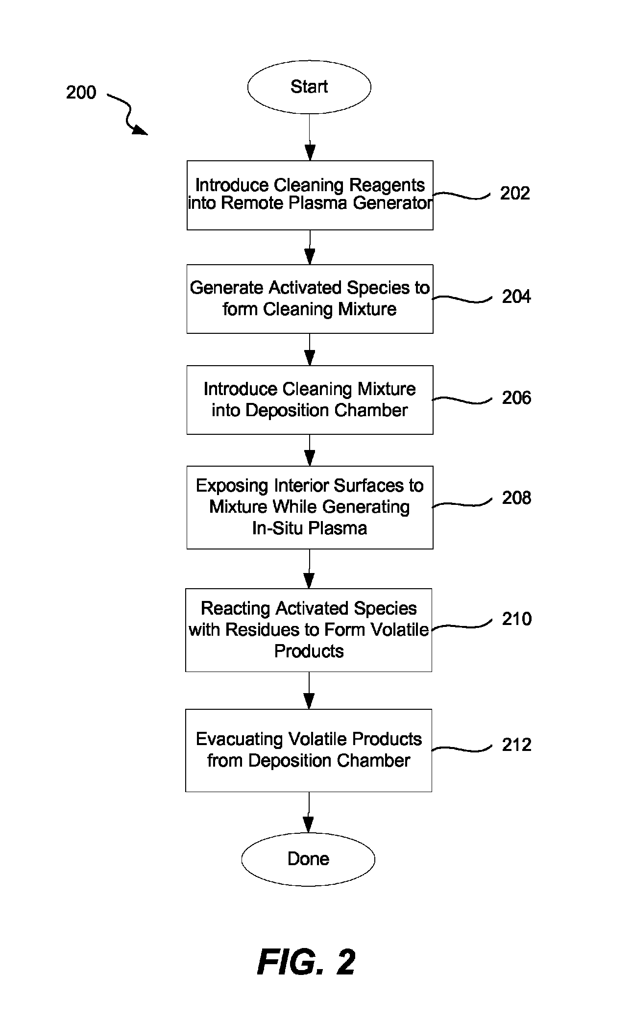
The patent describes a method of cleaning residues from deposition chambers using plasma generated from a remote plasma generator. A cleaning reagent is generated and introduced into the chamber where it etches the residue while forming removable byproducts that can be pumped away. RF power is applied to the clean mixture to generate an in-situ RF plasma which activates cleaning reagent molecules that have not previously been activated. This method provides improved cleaning efficiency.

Problems solved by technology

These residues can build up over time and dissolve, detach or otherwise disperse through the deposition chamber causing contamination.

Method used

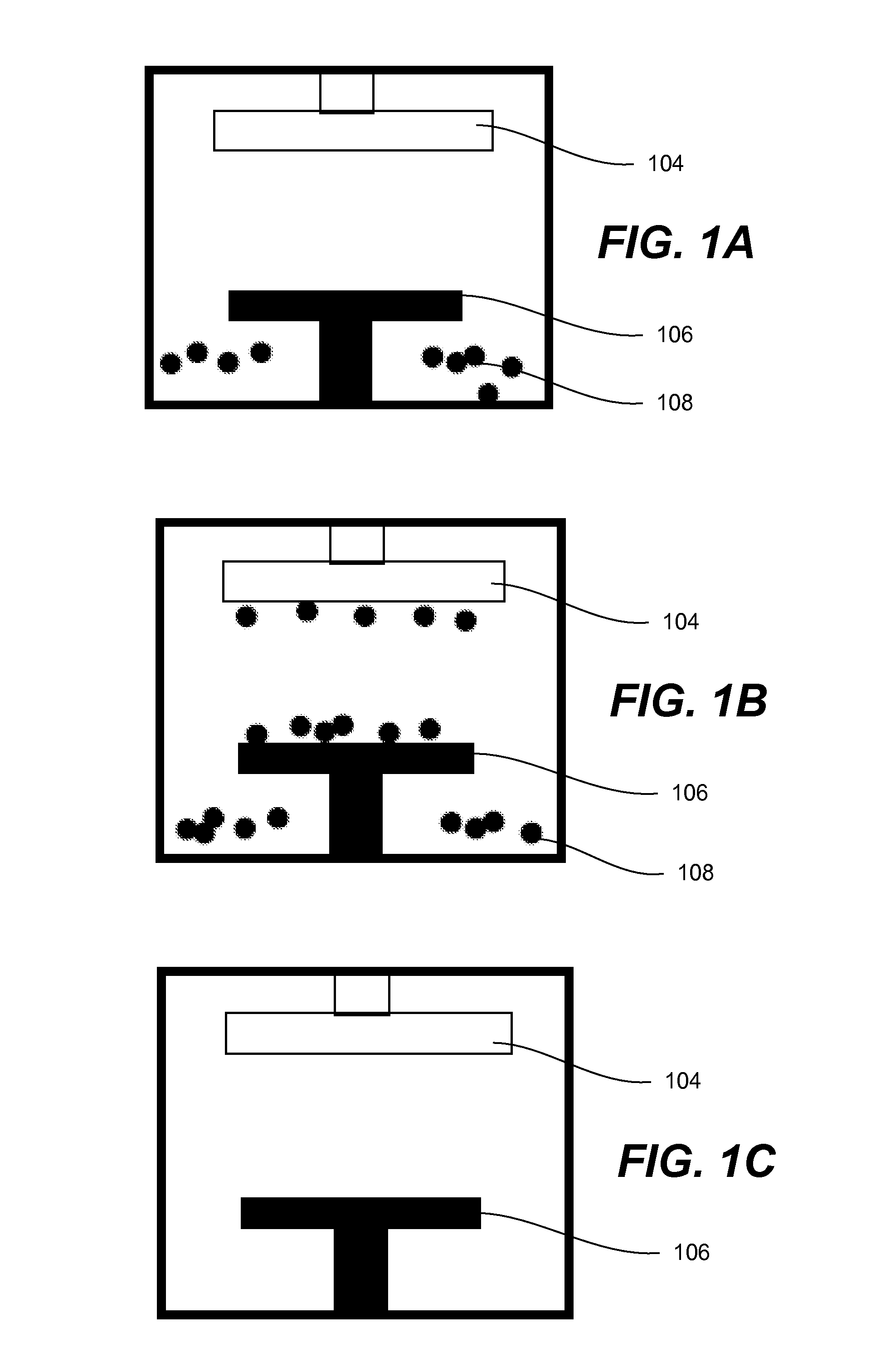
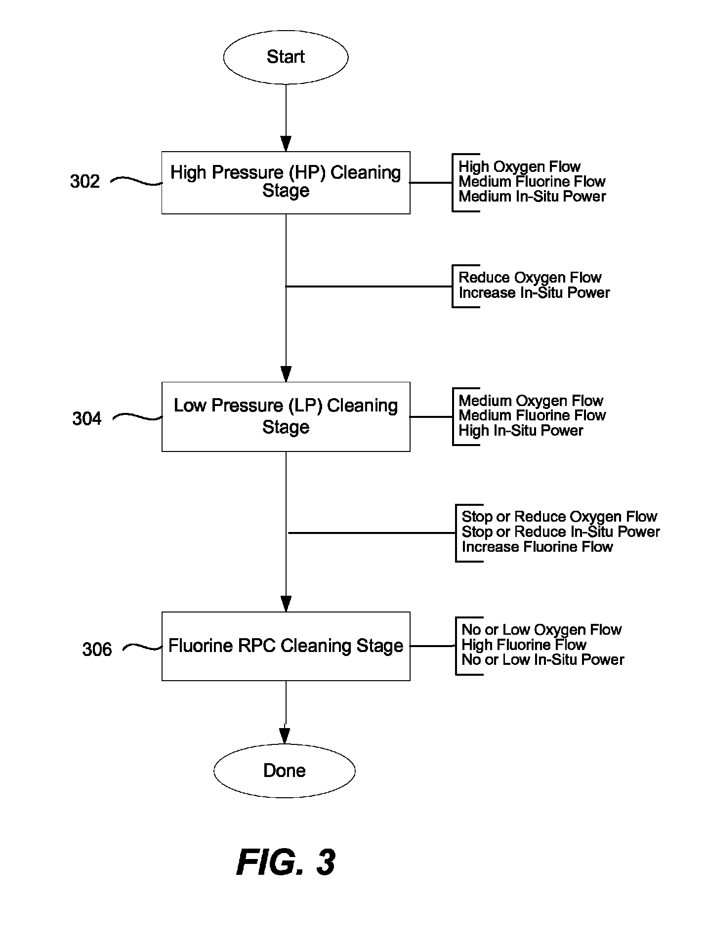

Image

  • Plasma clean method for deposition chamber
  • Plasma clean method for deposition chamber
  • Plasma clean method for deposition chamber

Examples


example 1

[0050]An experiment was conducted to compare effectiveness of etching an ashable hard mask film from the wafer surface using a cleaning method versus an in-situ cleaning method. Standard 300-mm wafers with 5,500 Å ashable hard mask film were divided into four separate groups. Each group was etched for about 30 seconds in a Vector PECVD deposition chamber using four different clean conditions. To evaluate effect of certain process parameters, the same temperature of about 350° C., the same pressure of about 0.45 Torr, and the same cleaning reagents were used for all groups. Nitrogen trifluoride was flown at 300 sccm and oxygen was flown at 6,000 sccm in all tests. The two cleaning reagents were flown simultaneously at the constant flow rates indicated above during the entire cleaning test. The process conditions were selected for comparison purposes only and were not representative of the optimal process parameters evaluated in the experiments below.

[0051]FIG. 5 is a plot illustratin...

example 2

[0054]Yet another experiment was conducted to using a Vector PECVD chamber. First, a set of ashable hard mask depositions was conducted to build up the film accumulation inside the chamber. Fifty wafers were deposited with approximately 5,500 Å thick ashable hard mask film at 350° C. The chamber was then cleaned using one of several proposed cleaning methods. An in-situ cleaning method with the clean parameters listed in the table below. A total of 26 min cleaning time to achieve adequate cleanness of the chamber, i.e. lack of any visible residues.

[0055]

TABLE 3HP CleanHP Clean 2LP CleanNF3 Flow Rate (sccm)6001000400O2 Flow Rate (sccm)600015001500He Flow Rate (sccm)030000HF Power Level (W)400030003250Pressure (Torr)1.01.50.25

[0056]The results of the in-situ cleaning were compared to results of several runs using a cleaning method. Three different settings were tested for the HF generator during the low pressure cleaning stage. The process parameters for the cleaning method are summar...


PUM

PropertyMeasurementUnit
Pressureaaaaaaaaaa
Angleaaaaaaaaaa
Angleaaaaaaaaaa

Abstract

Improved methods and apparatuses for removing residue from the interior surfaces of the deposition reactor are provided. The methods involve increasing availability of cleaning reagent radicals inside the deposition chamber by generating cleaning reagent radicals in a remote plasma generator and then further delivering in-situ plasma energy while the cleaning reagent mixture is introduced into the deposition chamber. Certain embodiments involve a multi-stage process including a stage in which the cleaning reagent mixture is introduced at a high pressure (e.g., about 0.6 Torr or more) and a stage the cleaning reagent mixture is introduced at a low pressure (e.g., about 0.6 Torr or less).

Description

FIELD OF THE INVENTION[0001]The present invention relates generally to methods and apparatuses for cleaning deposition chambers and more specifically to methods and apparatuses for cleaning residues from interior surfaces of deposition chambers using plasmas.BACKGROUND OF THE INVENTION[0002]Deposition of thin films is one of the key processes in semiconductor manufacturing. A typical wafer goes through deposition of several thin films, some of which may completely or partially remain in the final electronic device, while others may only temporarily remain on the wafer and serve some intermediate processing needs. For example, an ashable hard mask film may be used as an etch hardmask layer. Such film is first deposited on a wafer and then partially removed to define circuit line patterns. An etchant is then applied to remove some of the underlying dielectric forming trenches and vias for the future circuit lines. Eventually, all remaining ashable hard mask film is removed from the wa...

Claims


Application Information

Patent Timeline
IPC IPC(8): B08B9/08
CPCH01J37/32357C23C16/4405B08B7/0035H01J37/32862B08B9/00
Inventor FANG, ZHIYUANSUBRAMONIUM, PRAMODHENRI, JONFOX, KEITH
Owner NOVELLUS SYSTEMS
Learn More