
Floating ring gear epicyclic gear system

Inactive Publication Date: 2013-11-19
BOWMAN THOMAS W
View PDF19 Cites 28 Cited by
  • Summary
  • Abstract
  • Description
  • Claims
  • Application Information

AI Technical Summary

Benefits of technology

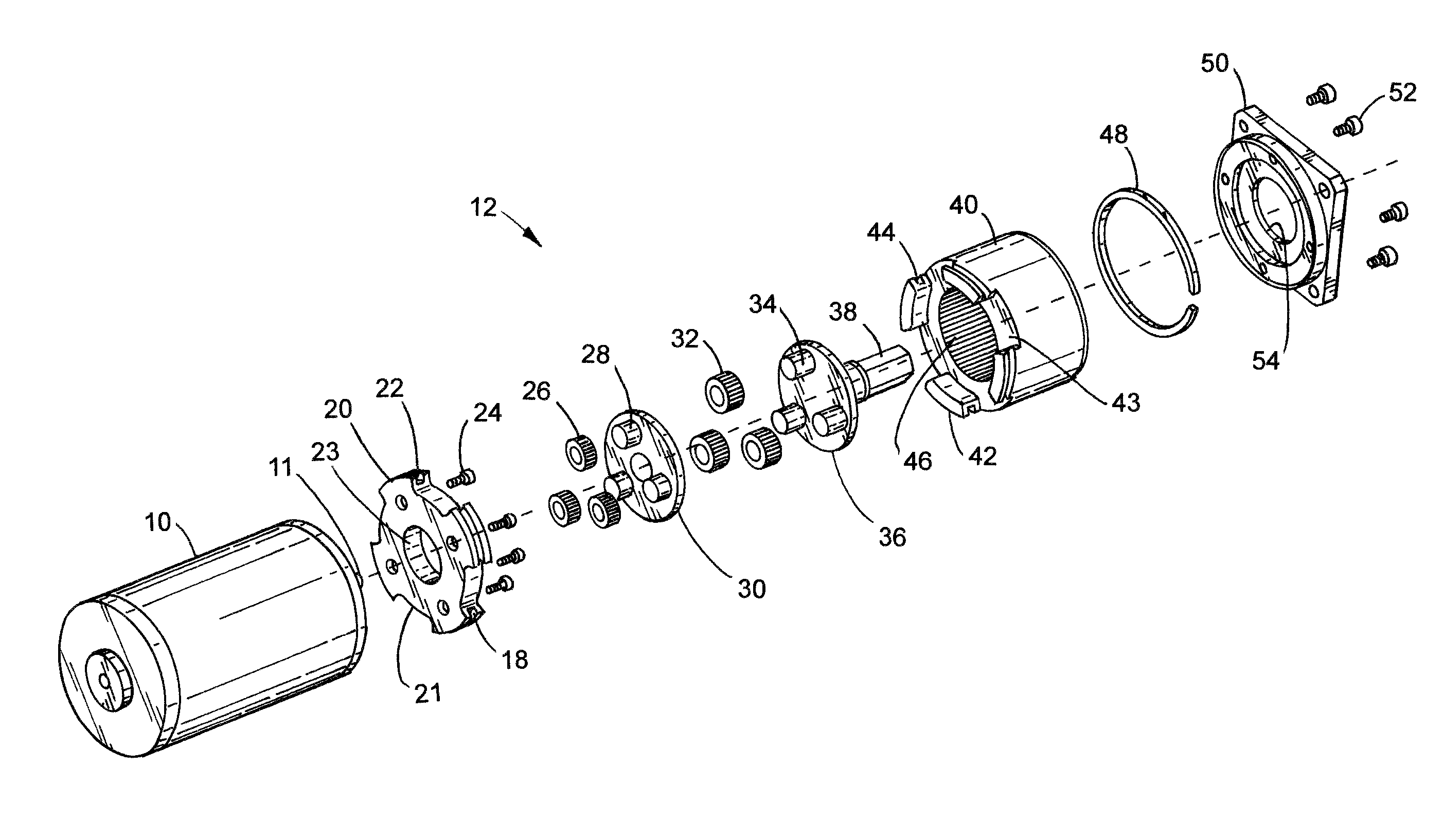
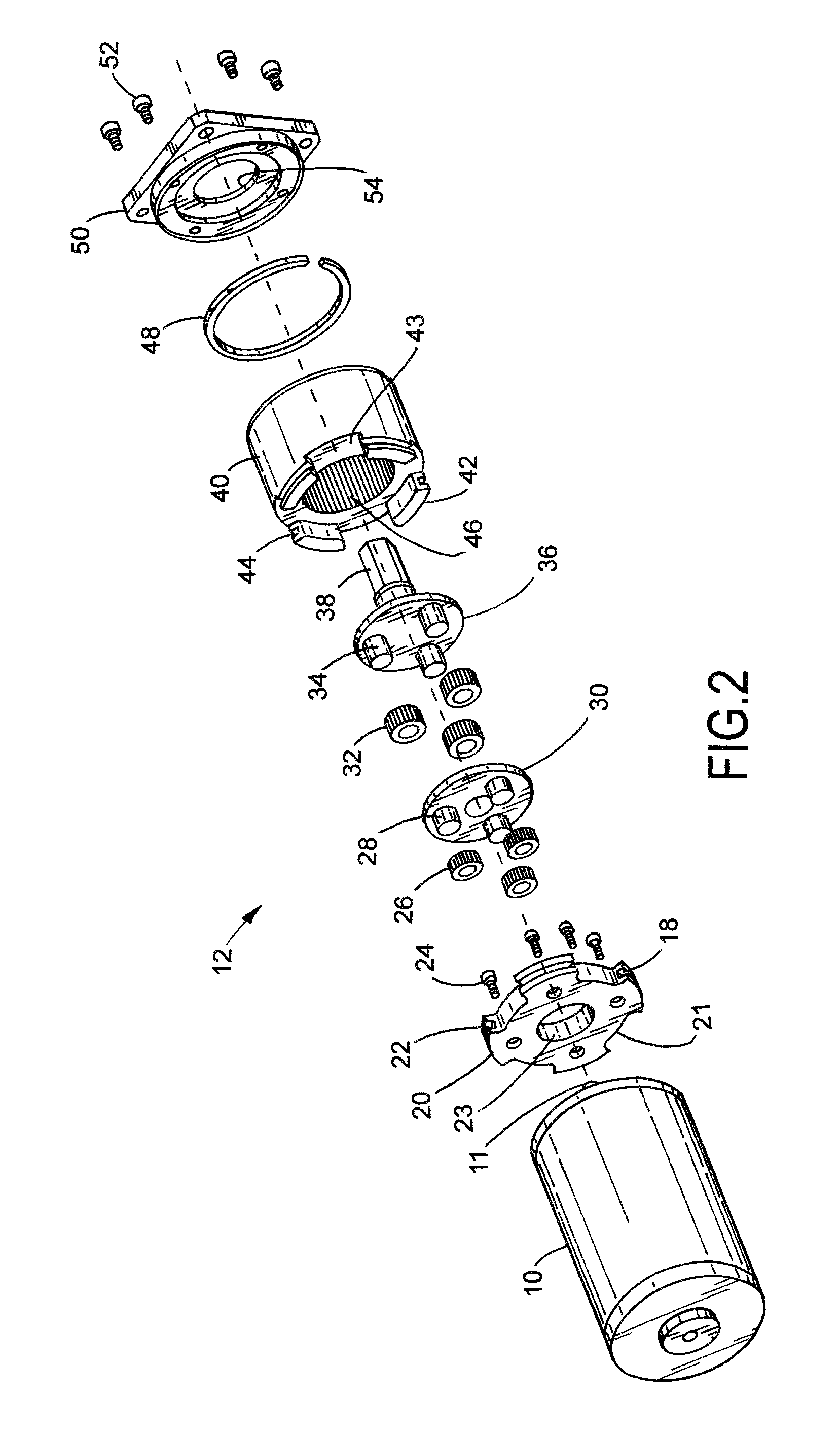
The invention is about a way to make small gears in a gear system that don't get stuck together during operation. The technique involves using a cap and a gear reducer body that move a little bit radially and axially with each other to reduce binding between the gears. The cap is fastened to a motor and the gear reducer body is held in place by a split retaining ring. The cap and gear reducer body are also made with interleaved castellations that allow them to move a small amount during rotation. The technique allows for better meshing of the gears and reduces the need for precision alignment between the housings. The invention also provides a method for manufacturing the gear system using the cap and gear reducer body.

Problems solved by technology

Machine “runout” is the error in the concentricity of a component that cannot be eliminated, but is inherent in milling machines and the like.
The higher precision the machine, the less runout is involved, but the cost of the product is correspondingly increased.
In some situations, the dimensional errors in the gear components cause an interference, in that the freedom of rotation is reduced as the tolerances can be additive at certain angular positions of rotation, thereby causing the gears to momentarily bind and require additional power to move the gears past the interfering position.
When the gears are large with correspondingly large teeth, the interference can be minimal as the increased meshing between the gear teeth does not cause a significant interference, and thus is generally unnoticeable.
However, when the gears are constructed with small diameters and correspondingly small teeth, the interference between out-of-round gears can cause substantial interference, thus requiring additional input power.
A non-uniform input power is thus required to cause the gears to rotate at a constant speed.
A smooth transfer of power between the input and the output is thus more difficult.
This situation is exacerbated in epicyclic gear systems where the planet gears not only rotate, but the axles of the planet gears also rotate, thus providing more opportunities for interferences between the three gear components.
Even when machining or otherwise forming gears with a high degree of accuracy, errors can be introduced into the gear system when assembled together.
The assembly errors and inaccuracies can be overcome by manufacturing the housings with a high degree of precision, but this significantly increases the overall cost of the gear system.

Method used


Image

  • Floating ring gear epicyclic gear system
  • Floating ring gear epicyclic gear system
  • Floating ring gear epicyclic gear system

Examples


Embodiment Construction

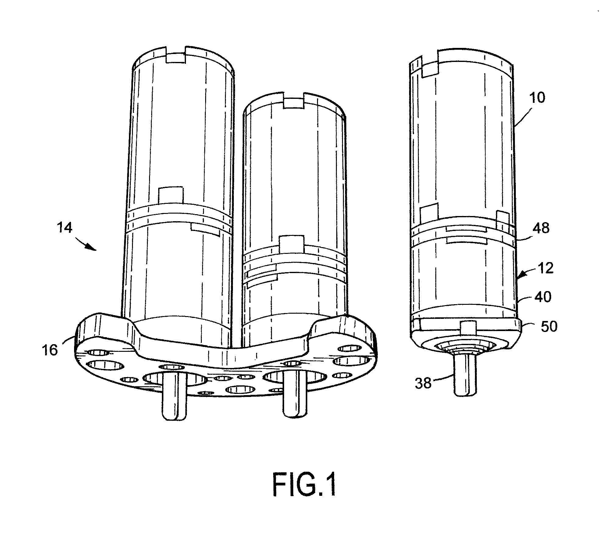
[0019]FIG. 1 illustrates a miniature DC motor, which is also shown mounted in an assembly 14 to a common mounting plate 16. In practice, the DC motors are employed in reinstatement cutters of the type that are transported in underground main pipes that have been reinstated with plastic liners. The cutting machine is equipped with a cutting bit that is remotely controlled to remove a plug of the plastic liner at a location where a lateral pipe is connected to the main pipe. The removal of the plastic area that covers the lateral opening to the main allows the waste water to flow from the lateral to the main. The cutting machine is operated with a video camera to allow the operator at the surface to not only move the reinstatement cutting machine along the main, but to also move the cutting bit in a circular path to cut and remove the plug from the plastic liner. Such types of reinstatement cutting machines are more thoroughly described in U.S. Pat. Nos. 7,249,918; 7,364,392 and 7,473...


PUM

PropertyMeasurementUnit
Lengthaaaaaaaaaa
Lengthaaaaaaaaaa
Diameteraaaaaaaaaa

Abstract

A small size epicyclic gear system in which the mating between gear housings is purposefully made with some play to allow a certain degree of relative movement to accommodate machining runout errors in the manufacture of the gears. A castellated cap fastened to the motor engages with a castellated gear reduction body. The tolerances built into the cap and gear reduction body allow relative radial movement therebetween to reduce binding of the gears during rotational positions in which the gear component runout tolerances are additive.

Description

RELATED APPLICATION[0001]This U.S. non-provisional patent application claims the benefit of U.S. provisional application Ser. No. 61 / 634,005, filed Feb. 22, 2012.TECHNICAL FIELD OF THE INVENTION[0002]The present invention relates in general to gear mechanisms, and more particularly to methods and apparatus for overcoming the adverse effects of variations in machining tolerances of the gear parts thereof.BACKGROUND OF THE INVENTION[0003]Planetary, or epicyclic, gear systems are well known for providing different rotational speeds between the input and the output. In epicyclic gear systems, one of the axles of the gears moves in a circular path. Depending on which part of the planetary gear system is driven with an input torque, the output can be a torque of either a higher rpm or a lower rpm. A typical epicyclic gear system includes two or more planet gears mounted to a carrier, a central sun gear that meshes with all of the planet gears, and an annular ring gear that also meshes wit...

Claims


Application Information

Patent Timeline
IPC IPC(8): B21D53/28F16H48/06
CPCF16H1/46F16H57/023F16H2057/0222Y10T29/49464
Inventor BOWMAN, THOMAS W.
Owner BOWMAN THOMAS W
Learn More