
Pulse width modulation controller and method for output ripple reduction of a jittering frequency switching power supply

a jittering frequency switching power supply and output ripple technology, applied in the field of switching power supply, can solve the problems of overcompensation at light load, excessive output ripple, and loss of the switching power switch, and achieve the effect of reducing output ripple and improving output ripple caused by the jittering frequency of the switching power supply

Active Publication Date: 2013-11-12
RICHTEK TECH
View PDF17 Cites 15 Cited by
  • Summary
  • Abstract
  • Description
  • Claims
  • Application Information

AI Technical Summary

Benefits of technology

[0007]An objective of the present invention is to provide a pulse width modulation controller and method for reducing an output ripple caused by a jittering frequency of a switching power supply.
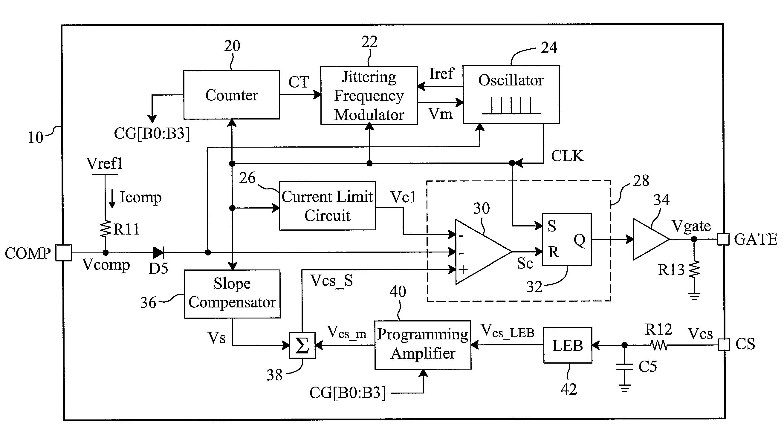
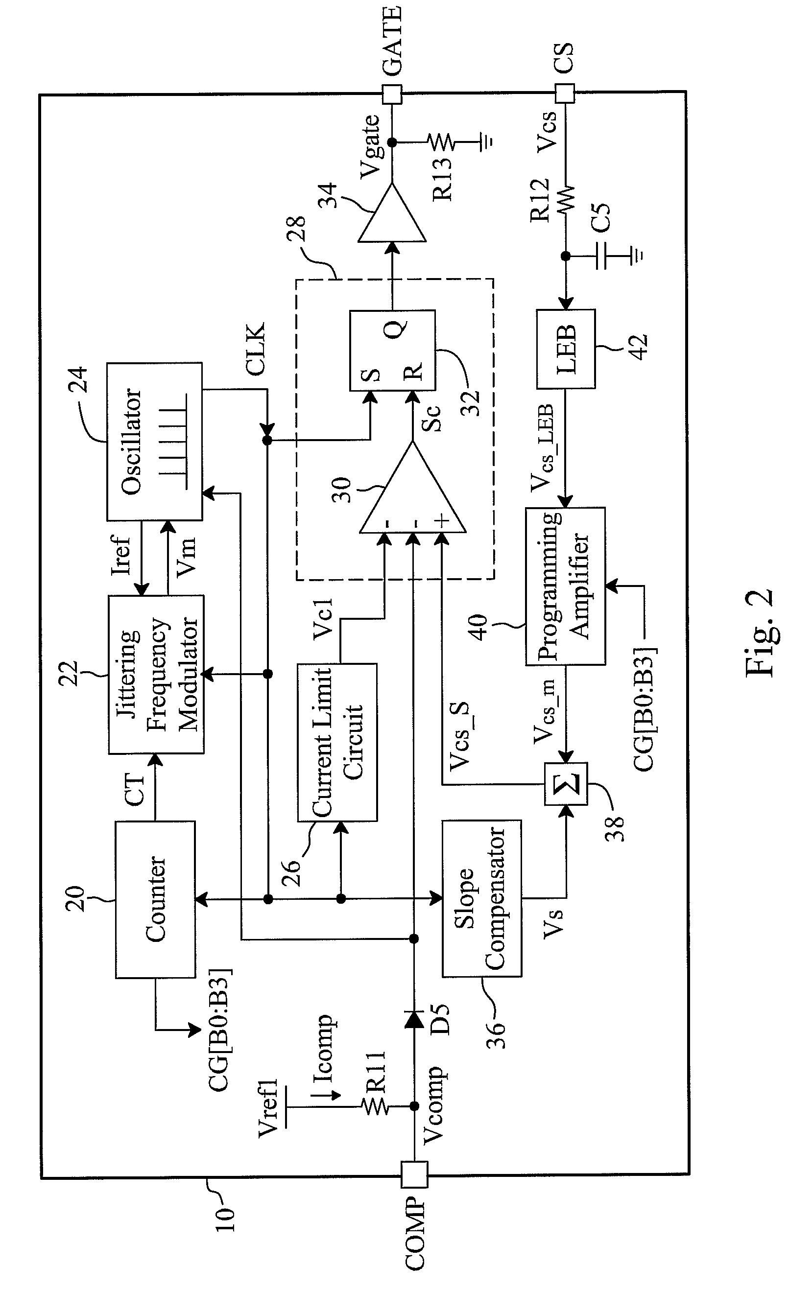
[0008]According to the present invention, a PWM controller and method for output ripple reduction of a jittering frequency switching power supply extract a current sense signal related to a current of a power switch of the switching power supply, and adjust a gain or the level of the current sense signal according to the switching frequency of the power switch to adjust the on-time of the power switch. Consequently, the output ripple caused by the jittering frequency of the switching power supply is improved.

Problems solved by technology

When a switching power supply is working at light load or in standby mode, the switching loss of its power switches accounts for a significant proportion of the overall power consumption.
Moreover, switching power supplies, though advantageously more compact than conventional linear power supplies, have another problem that electro-magnetic interference (EMI) caused by the switching elements.
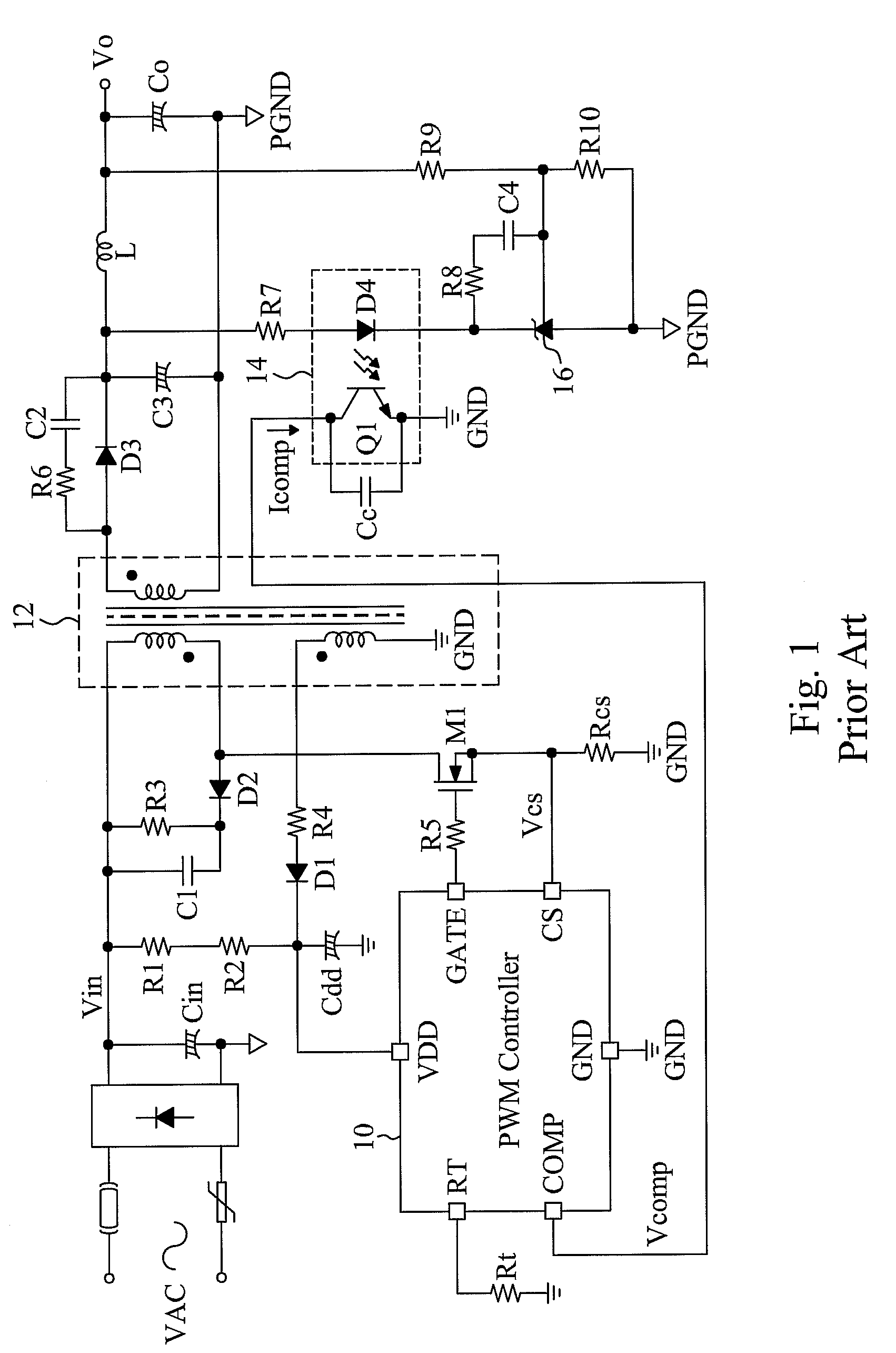
As shown by the equation Eq-1, jittering of the switching frequency fs causes variation in the output power Po to generate a low-frequency ripple at the output Vo of the flyback power supply, resulting in excessive output ripple.
However, the level of the feedback voltage Vcomp at light load is different from that at heavy load; the constant proportional adjust current may lead to overcompensation at light load.

Method used


Image

  • Pulse width modulation controller and method for output ripple reduction of a jittering frequency switching power supply
  • Pulse width modulation controller and method for output ripple reduction of a jittering frequency switching power supply
  • Pulse width modulation controller and method for output ripple reduction of a jittering frequency switching power supply

Examples


Embodiment Construction

[0016]Referring to the PWM controller 10 shown in FIG. 2. As in the known PWM loops, an oscillator 24 provides a clock CLK, a pulse width modulator 28 generates a switch signal Q responsive to the clock CLK, a feedback voltage Vcomp and a current sense signal Vcs S, a gate driver 34 generates a switch signal Vgate according to the switch signal Q, and the switching frequency of the switch signal Vgate is equal to the frequency fs of the clock CLK. A counter 20 counts the clock CLK to generate a count value CT, and a jittering frequency modulator 22 provides a jittering frequency adjust signal Vm to the oscillator 24 according to the count value CT, the clock CLK and a reference signal Iref provided by the oscillator 24. According to the feedback voltage Vcomp, the oscillator 24 controls the frequency fs of the clock CLK to vary with load. Also, the oscillator 24 determines a jittering frequency range of the clock CLK according to the jittering frequency adjust signal Vm. In the puls...


PUM


Abstract

A pulse width modulation controller and method for output ripple reduction of a jittering frequency switching power supply detect the current of a power switch of the switching power supply to generate a current sense signal, and adjust the gain or the level of the current sense signal according to the switching frequency of the power switch to adjust the on time of the power switch, to reduce the output ripple of the switching power supply caused by the jittering frequency of the switching power supply.

Description

FIELD OF THE INVENTION[0001]The present invention is related generally to a switching power supply and, more particularly, to a circuit and method for output ripple reduction of a jittering frequency switching power supply.BACKGROUND OF THE INVENTION[0002]Pulse width modulation (PWM) has been extensively applied to various electronic devices. For example, PWM controllers are used in switching power supplies to modulate duty cycles or switching frequencies of power switches and thereby modulate output voltages.[0003]Recently, due to energy shortages and the increasing awareness of environmental protection, the energy saving feature of switching power supplies has drawn more and more attention. At the same time, laws and regulations were passed to impose stricter requirements on the power conversion efficiency of switching power supplies at light load and in standby mode. When a switching power supply is working at light load or in standby mode, the switching loss of its power switche...

Claims


Application Information

Patent Timeline
Patent Type & Authority Patents(United States)
IPC IPC(8): H02M1/12H02M3/335
CPCH02M1/14H02M3/33507H02M2001/0025H02M1/0025
Inventor LIN, KUN-YULIN, TZU-CHENHUANG, PEI-LUN
Owner RICHTEK TECH
Learn More