Common key block encryption device, common key block encryption method, and program
a key block encryption and encryption method technology, applied in the field of common key block encryption devices and common key block encryption methods, to achieve the effect of more processing tim
- Summary
- Abstract
- Description
- Claims
- Application Information
AI Technical Summary
Benefits of technology
Problems solved by technology
Method used
Image

Examples
exemplary embodiment 1
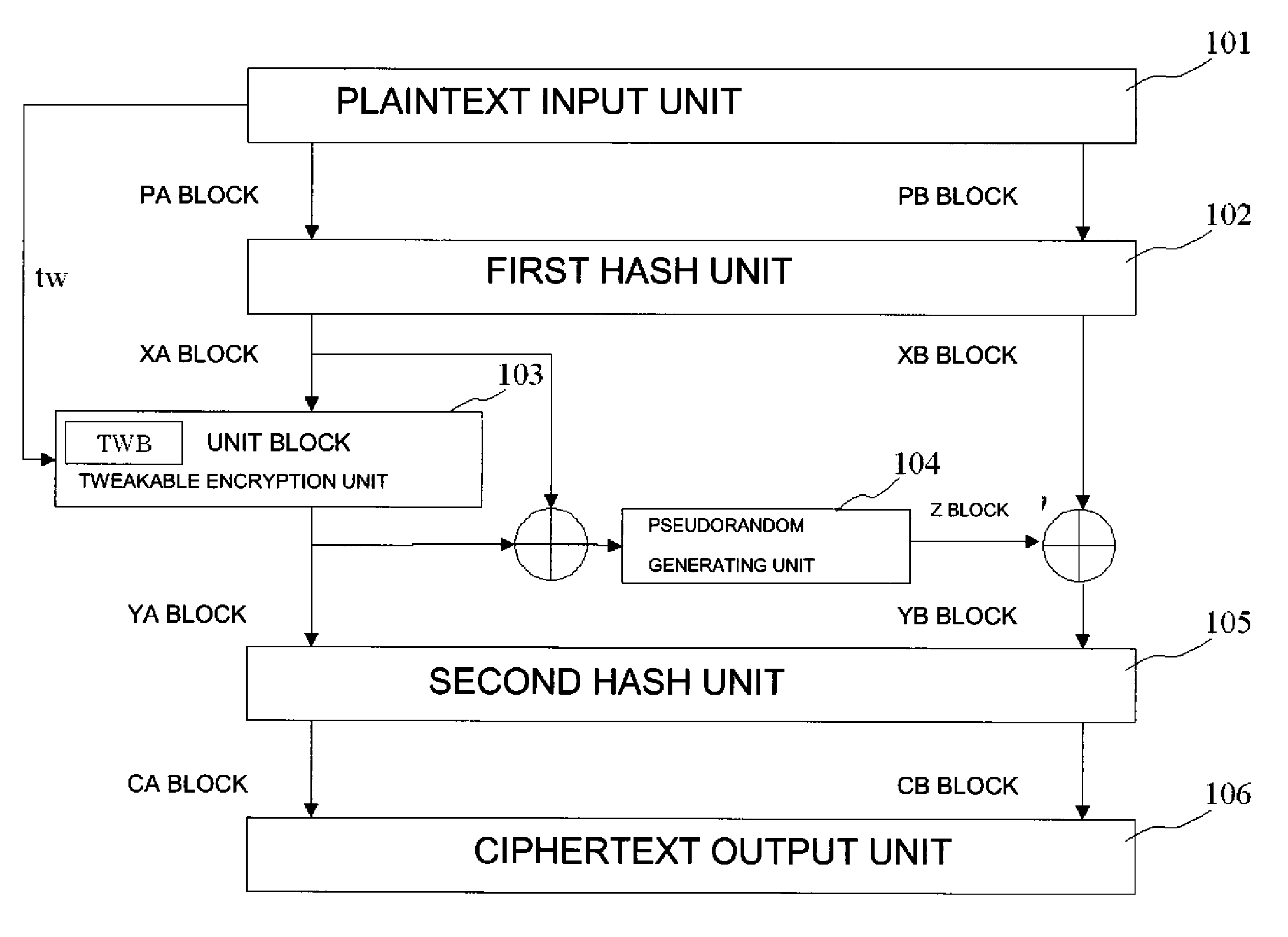
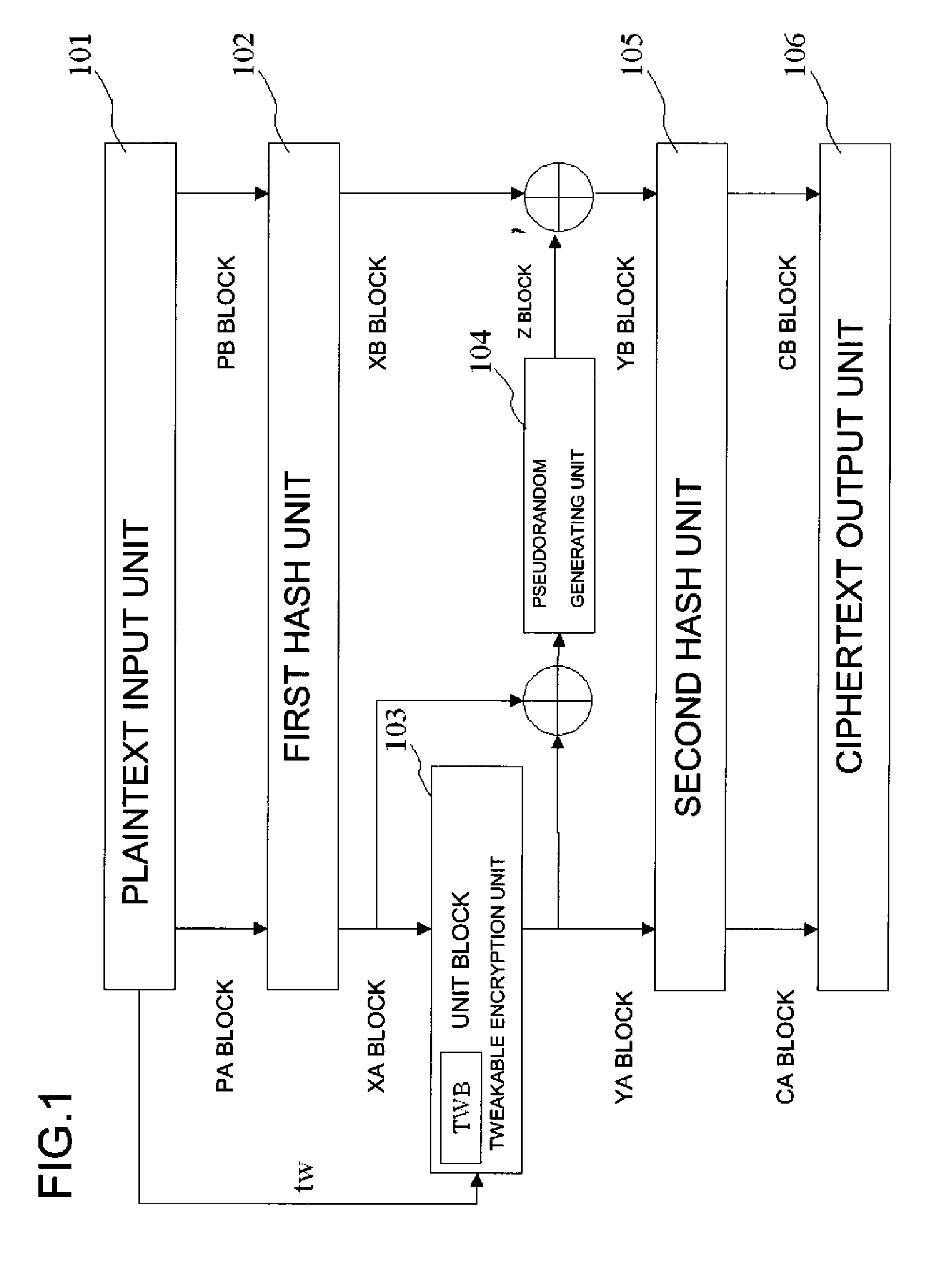
[0080]FIG. 1 is a block diagram showing the configuration of a common key block encryption device relating to a first exemplary embodiment of the present invention. In FIG. 1, the common key block encryption device relating to the first exemplary embodiment of the present invention includes plaintext input means 101, first hash means 102, unit block tweakable encryption means 103, pseudorandom number generating means 104, second hash means 105, and ciphertext output means 106. Among these, each of the first hash means 102, the unit block tweakable encryption means 103, pseudorandom number generating means 104, and the second hash means 105, and group processing shown in FIG. 1 are realized by a program that has a computer function as each of the above-mentioned means.
[0081]The plaintext input means 101 inputs a tweak value tw and an s-bit plaintext (the PA block and the PB block), an encryption target. The plaintext input means 101 is realized by, for instance, a character input dev...
exemplary embodiment 2
[0114]Next, a second exemplary embodiment of the present invention, in which the pseudorandom number generating means 104 of the first exemplary embodiment is modified, will be described. FIG. 3 is a block diagram showing the configuration of a common key block encryption device relating to the second exemplary embodiment of the present invention. In FIG. 3, the common key block encryption device relating to the second exemplary embodiment of the present invention comprises the plaintext input means 101, the first hash means 102, the unit block tweakable encryption means 103, pseudorandom number generating means 104a, the second hash means 105, and the ciphertext output means 106.
[0115]Since each of the plaintext input means 101, the first hash means 102, the unit block tweakable encryption means 103, the second hash means 105, and the ciphertext output means 106 in FIG. 3 is identical to the respective means in the first exemplary embodiment, the explanations of them will be omitte...
exemplary embodiment 3
[0122]Next, a third exemplary embodiment of the present invention using a stream cipher as the pseudorandom number generating means of the first exemplary embodiment above will be described. Since each constituent of the present exemplary embodiment is identical to each means of the first exemplary embodiment except for the pseudorandom number generating means, the explanations of them will be omitted, and how the pseudorandom number Z block is generated by the pseudorandom number generating means will be described in detail below.
[0123]The pseudorandom number generating means (the second encryption processing means) (104 in FIG. 1) in the present exemplary embodiment receives the sum of the XA block and the YA block or the result of an arbitrary group computation as input, and generates the pseudorandom number Z block, using a stream cipher. More concretely, the pseudorandom number generating means (104 in FIG. 1) is required to be an additive stream cipher accepting an n-bit IV an...
PUM
 Abstract
Description
Claims
Application Information
 - R&D
- Intellectual Property
- Life Sciences
- Materials
- Tech Scout
- Unparalleled Data Quality
- Higher Quality Content
- 60% Fewer Hallucinations
Browse by: Latest US Patents, China's latest patents, Technical Efficacy Thesaurus, Application Domain, Technology Topic, Popular Technical Reports.
© 2025 PatSnap. All rights reserved.Legal|Privacy policy|Modern Slavery Act Transparency Statement|Sitemap|About US| Contact US: help@patsnap.com